Trim tab position monitor

a position monitor and tab position technology, applied in the direction of instruments, special-purpose vessels, vessel construction, etc., can solve the problems of device corrosion and potential damage effects, and the effect of being particularly deleterious

Inactive Publication Date: 2003-06-24
BRUNSWICK CORPORATION
View PDF8 Cites 42 Cited by
  • Summary
  • Abstract
  • Description
  • Claims
  • Application Information

AI Technical Summary

Benefits of technology

It should be understood that the present invention actually provides an output signal that represents the physical condition of the point at which the trim tab is connected to a moveable actuator that is driven by the rotor of the motor. This output signal may represent a magnitude that has a nonlinear relationship to the physical angle of the trim tab relative to the transom of a marine vessel. As will be described in greater detail below, an output device or output monitor can be provided with a conversion table that easily converts the output received from the present invention to an angle representing the resulting angle between the trim tab and the transom of the boat or, alternatively, an angle between the trim tab and a horizontal plane.
In a particularly preferred embodiment of the present invention, the signal output device is connected in signal communication with the counter and in signal communication with a boat position annunciator. The boat position annunciator can be a visual display for the operator of the marine vessel. In certain embodiments of the present invention, the rotor of the motor is operatively attached to a threaded shaft which rotates in response to rotation of the rotor. The threaded shaft can be operatively connected to the trim tab, whereby rotation of the rotor causes the threaded shaft to rotate and rotation of the threaded shaft causes the trim tab to move relative to the stator of the motor as it pivots about a pivot point attached to the transom of a marine vessel.

Problems solved by technology

When position sensing devices are located at or near the trim tabs themselves, those devices are subjected to the corrosive and potential damaging effects of submersion in water.
These effects can be particularly deleterious when a marine vessel is operated in salt water.

Method used


Image

  • Trim tab position monitor
  • Trim tab position monitor
  • Trim tab position monitor

Examples


Embodiment Construction

Throughout the description of the preferred embodiment of the present invention, like components will be identified by like reference numerals.

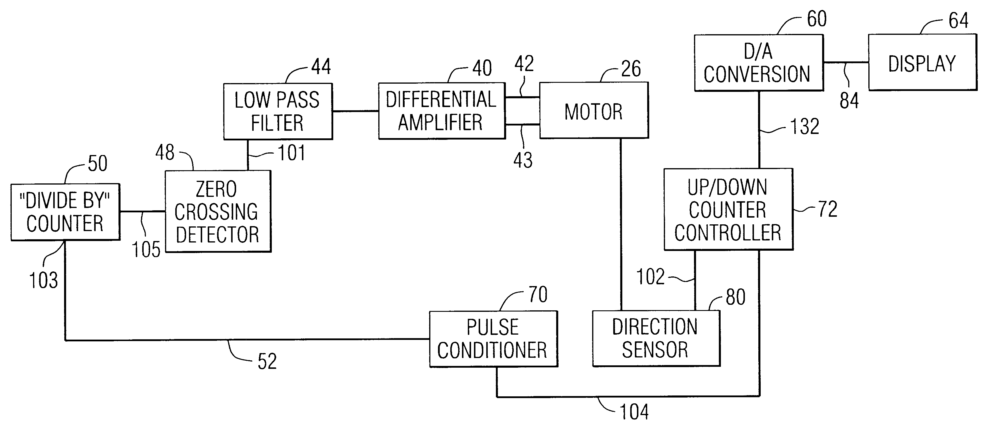
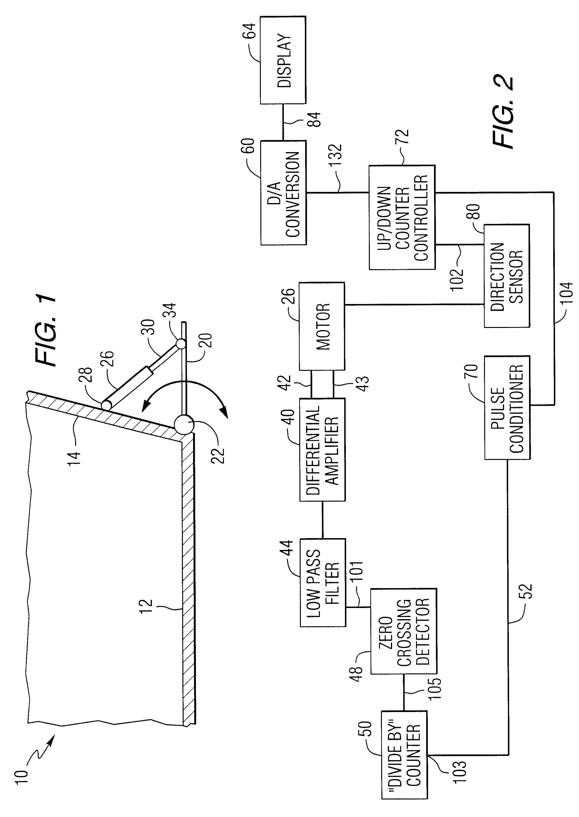
FIG. 1 is an exemplary illustration of a marine vessel 10 having a hull 12 and a transom 14. The marine vessel shown in FIG. 1 has a trim tab 20 which is rotatably attached to the transom 14 at a pivot point identified by reference numeral 22. A motor 26 has a stator and a rotor within a housing structure. The housing of the motor 26 is pivotally attached, at point 28, to the transom 14. An actuator 30 is associated with the rotor of the motor 26. The actuator 30 is connected to the trim tab 20, at point 34, so that extension of the actuator 30 away from the motor 26 causes the trim tab 20 to rotate about pivot point 22. In a particularly preferred embodiment of the present invention, the rotor of the motor 26 is associated with the actuator 30 in such a way that a threaded portion of the actuator 30 is caused to move into the motor 26 or out...


PUM


Abstract

A trim tab monitoring circuit is provided which receives a signal that is representative of a voltage potential across a stator winding of a motor which is attached to the trim tab. This signal is passed through a high pass filter to remove the DC component of the signal, amplified, and passed through a low pass filter to remove certain high frequencies components of the signal. A zero crossing detector is used to discern individual pulses which are then received by a counter that provides a single output pulse for a predetermined number of input pulses. The series of output pulses from the counter are conditioned and, in conjunction with a direction sensor, provided to an up / down counter controller that provides digital signals to a signal output circuit. The signal output circuit provides a DC voltage output to a display and the DC output voltage is representative of the position of the trim tab.

Description

BACKGROUND OF THE INVENTION1. Field of the InventionThe present invention is generally related to a trim tab position monitor and, more particularly, to a monitoring circuit which determines the position of a trim tab of a marine vessel by determining the number of changes in magnitude of an electrical characteristic of a motor which is attached to the trim tab.2. Description of the Prior ArtMany different ways are known for measuring the angular position of a trim tab relative to a transom of a marine vessel.U.S. Pat. No. 4,420,741, which issued to West on Dec. 13, 1983, describes a trim tab position monitor and display device. An electric position monitor and read out device for trim tabs on boats is described in which the monitor and read out device are connected to the trim tab controls. The device is electronic and position display is based on the time required for trim tab movement. Signals from the trim tab controls produce signals from timers which in turn are directed to en...

Claims


Application Information

Patent Timeline
IPC IPC(8): B63B39/00B63B39/06G01D5/245G01D5/12
CPCG01D5/2451B63B39/061
Inventor STAERZL, RICHARD E.
Owner BRUNSWICK CORPORATION
Why Eureka
Try Eureka