Electronic timepiece

a technology of electronic timepieces and contact points, applied in the direction of electric windings, instruments, horology, etc., can solve the problems of significant space needed in electronic timepieces, inability to accurately display time or calendar displays, and difficulty in positioning the proportion of contact points which contact with contact points pattern

Inactive Publication Date: 2003-06-24
SEIKO INSTR INC
View PDF27 Cites 13 Cited by
  • Summary
  • Abstract
  • Description
  • Claims
  • Application Information

AI Technical Summary

Problems solved by technology

However, in the conventional electronic timepiece, there were the problems which follow.
(1) Since the contact point spring was formed of material which was easy to flex, the portion of the contact point spring which contacted with the contact point pattern was difficult to position.
(2) In order to dispose the contact point spring having a sufficient spring length, a significantly large space was needed in the electronic timepiece.
(3) When the portion of the contact point spring which contacts with the contact point pattern is disposed at a position which is farther away from the contact point pattern than necessary, even when the hour wheel rotates, the contact point spring cannot be contacted with the contact point pattern of the circuit block by the conduction pin, with the result that time display or calendar display becomes unable to be accurately made.
(4) When the portion of the contact point spring which contacts with the contact point pattern is disposed at a position which is nearer to the contact point pattern than necessary, when the hour wheel has rotated, the pressure of the contact point spring applied to the conduction pin be

Method used


Image

  • Electronic timepiece
  • Electronic timepiece
  • Electronic timepiece

Examples


eighth embodiment

(10) Structure and Function of Electronic Timepiece of the Invention

Next, an explanation will be given of the structure of the calendar mechanism of the electronic timepiece according to an eighth embodiment of the present invention.

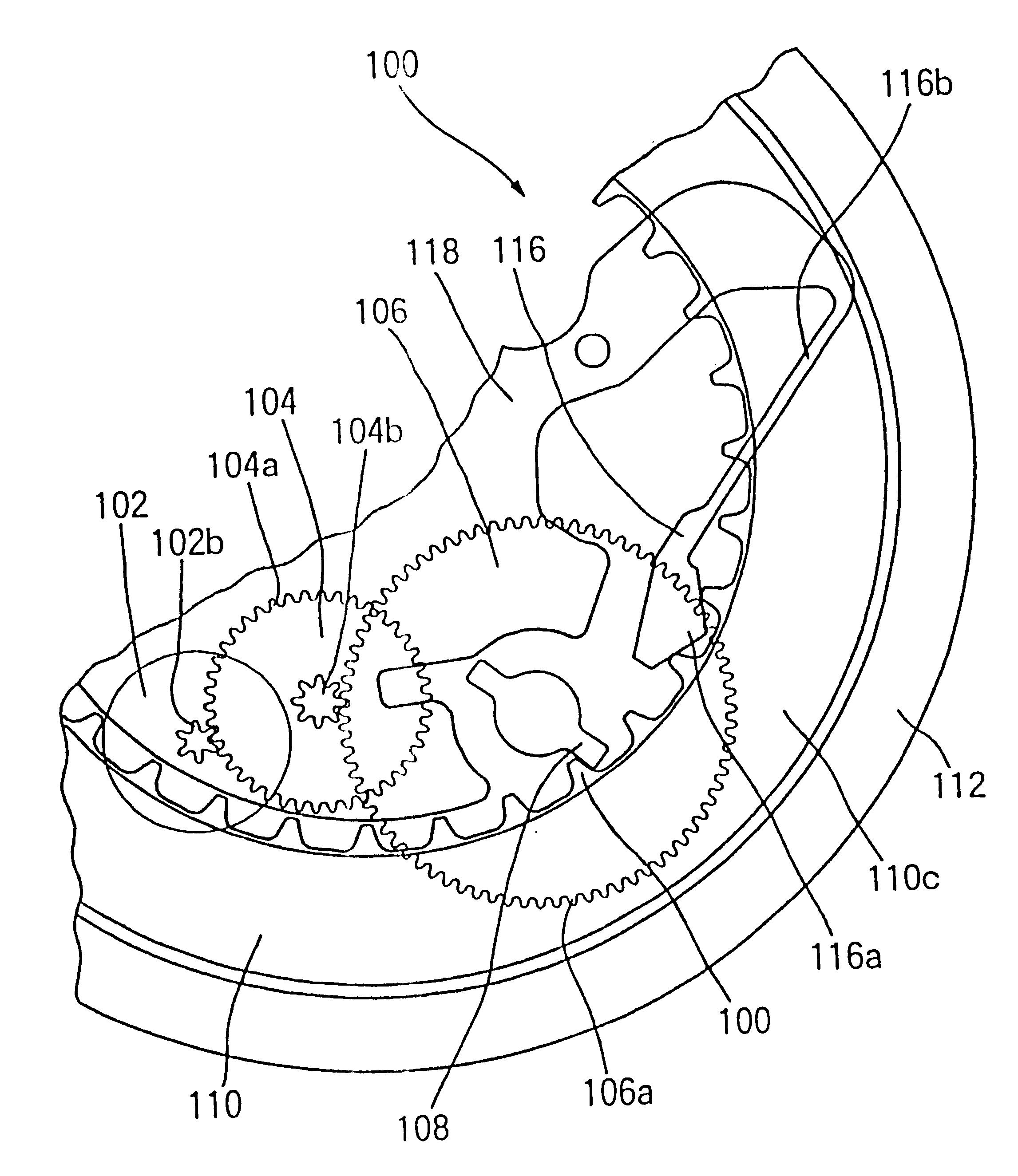
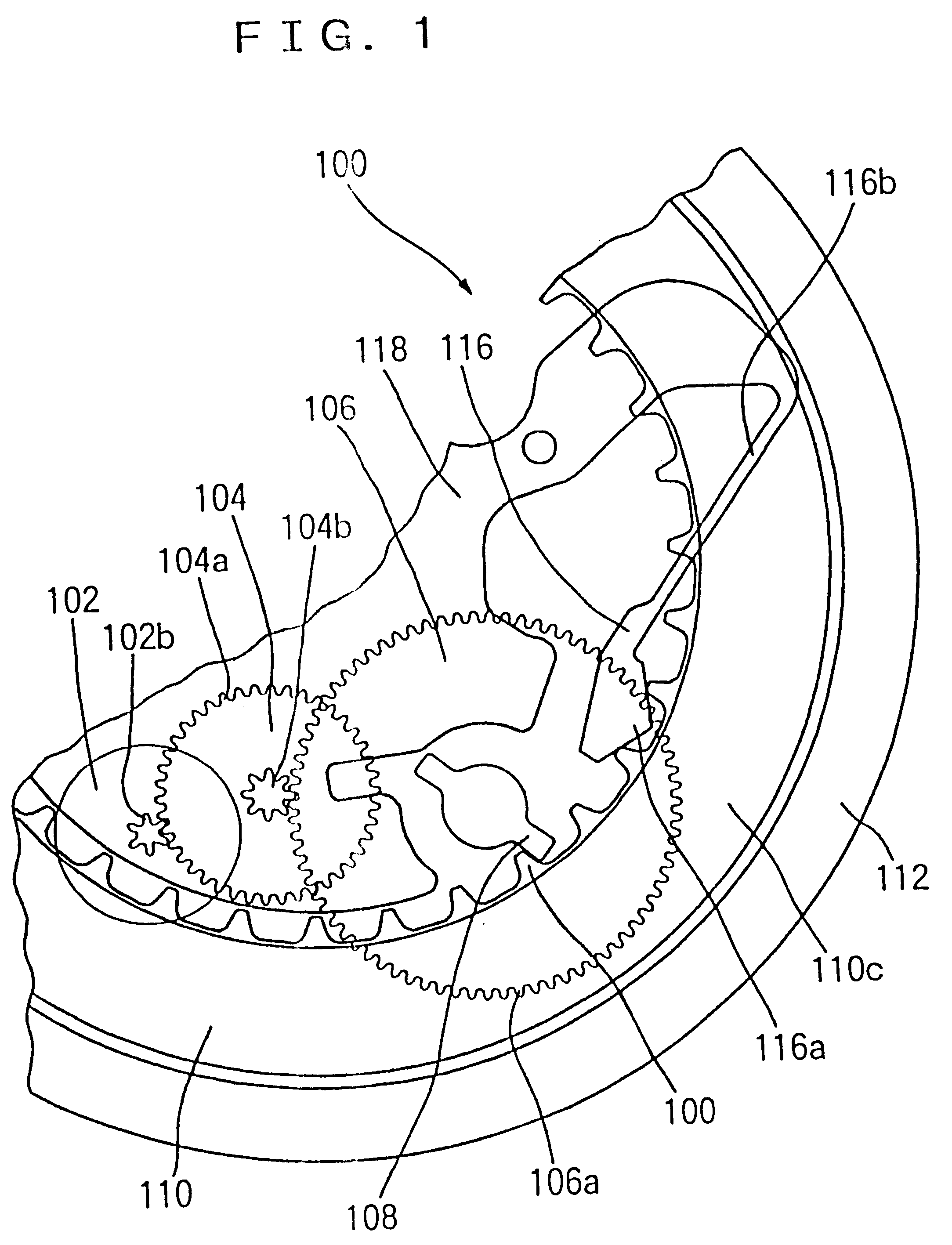
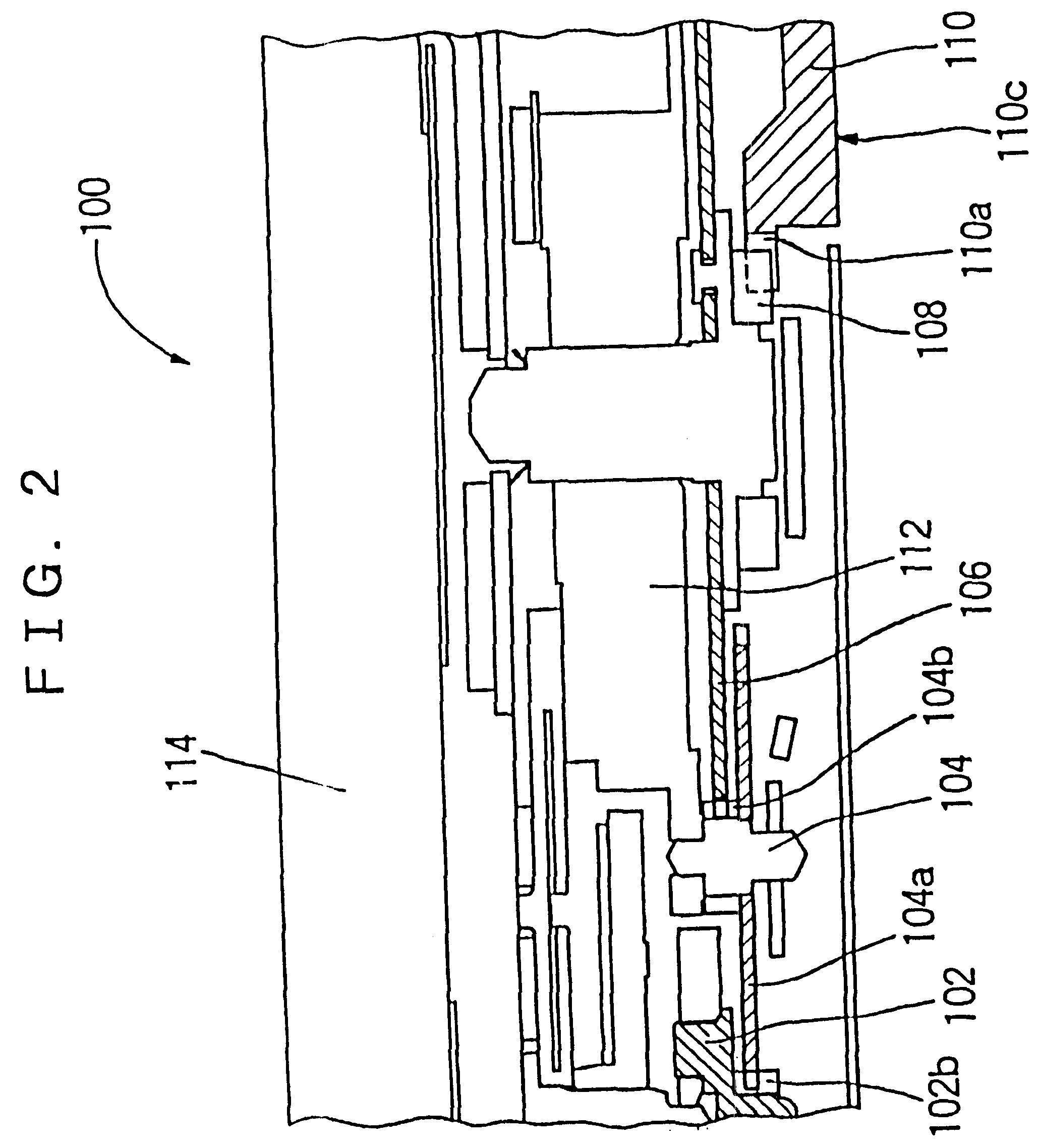
Referring to FIG. 47, according to the eighth embodiment of the present invention, in the calendar-equipped electronic timepiece 1400, an ultrasonic motor (not illustrated) is used as the motor for rotating the date dial 1410. This ultrasonic motor includes an ultrasonic rotor. An ultrasonic rotor pinion of the ultrasonic rotor is meshed with the intermediate date driving gear of the intermediate date driving wheel 1404. An intermediate date driving pinion of the intermediate date driving wheel 1404 is meshed with a date driving gear of the date driving wheel 1406.

The date finger 1408 is provided on the date driving wheel 1406 and, when the date driving wheel 1406 is rotated, is rotated simultaneously therewith. The date finger 1408 includes four date f...

fifth embodiment

As in the case of the above-described fifth embodiment of the present invention, the contact point spring is provided on the date driving wheel 1404 and it is arranged that the state of rotation of the date driving wheel 1406 is detected by the mutual contact between the contact point pattern of the printed circuit board and the contact point spring. And, it is arranged that the motor drive circuit controls the rotation of the ultrasonic motor by inputting the rotation signal output from the contact point pattern.

It is arranged that the date jumper 1416 regulates the position in the rotation direction of the date dial 1410 so that one date dial tooth 1410d of the date dial 1410 may be located on a straight line 1408A passing through a rotation center 1410k of the date dial 1410 and a rotation center 1408c of the date finger 1408.

In a state where the ultrasonic motor is being stopped, the two date finger portions 1408g1 and 1408g2 of the four date finger portions are positioned symme...

seventh embodiment

In the electronic timepiece 1400, in the same way as in the present invention explained in connection with FIGS. 42 and 43, through the rotation of the date driving wheel 1406, the first contact point portion 1160a and the second contact point portion 1160b can contact with the reference potential pattern 1174a and the contact point switch pattern 1174b in the order mentioned. And, as illustrated in FIG. 42, in a state where both of the first contact point portion 1160a and the second contact point portion 1160b contact with the reference potential pattern 1174a, no rotation signal is output.

In contrast to this, as illustrated in FIG. 43, in a state where the first contact point portion 1160a contacts with the reference potential pattern 1174a and the second contact portion 1160b contacts with the contact point switch pattern 1174b, the rotation signal is output. Similarly, in a state where the first contact point portion 1160a contacts with the contact point switch pattern 1174b an...


PUM


Abstract

To provide an electronic timepiece enabling reliable detection of a state of rotation of an indication wheel such as a date dial.An ultrasonic motor 1130 has an ultrasonic rotor pinion 1134b. A date dial 1120 is disposed on a main plate 1102 in such a way as to rotate relative thereto. The ultrasonic rotor pinion 1134b is meshed with an intermediate date driving gear wheel 1142a. A date driving wheel 1150 is rotatably disposed on the main plate 1102. A date driving gear wheel 1150b is meshed with an intermediate date driving pinion 1142b. A date driving gear portion 1150b is meshed with a dial gear portion 1120a. A contact point spring 1160 is disposed on a spring guiding portion 1150d. The contact point spring 1160 rotates integrally with the date driving wheel 1150 through the rotation of the date driving wheel 1150. The state of rotation of the date driving wheel 1150 can be detected by contact of the contact point spring 1160 with the contact point pattern 1174.

Description

1. Field of the InventionThe present invention relates to an electronic timepiece having a transmission wheel rotation position detecting unit which detects the position in the rotation direction of a transmission wheel of the electronic timepiece contained in a wheel train thereof such as an obverse wheel train or calendar wheel train.2. Description of the Prior ArtIn a conventional electronic timepiece, as illustrated in FIG. 38, a part of an obverse wheel train 930, e.g., a 24-hour contact point 932 for detecting a rotational position of the obverse wheel train 930 is provided on an hour wheel. When the 24-hour contact point 932 detects the position corresponding to the time of twelve o'clock at night, according to a detection signal output from the 24-hour contact point 932 a circuit block 934 rotates a date driving motor 936. Due to the rotation of the date driving motor 936, a date dial 912 is rotated through a reduction wheel train 938. This makes it possible to change the di...

Claims


Application Information

Patent Timeline
IPC IPC(8): G04C3/00G04C17/00G04C3/12
CPCG04C17/0066G04C3/12
Inventor NAKAJIMA, KENICHISATODATE, TAKAYUKIMATOUGE, AKIHIROINADA, AKIHIKOISHII, MITSURUKOYAMA, YOSHIOSUZUKI, SHIGEOKAWATA, MASAYUKISASAKI, YUKOTAKAKUWA, ERIKO
Owner SEIKO INSTR INC
Why Eureka
Try Eureka