Flashlight and flashlight electrical connectors

a technology of flashlights and electrical connectors, which is applied in the field of flashlights, can solve the problems of limiting the current flow to the illumination source, requiring a large amount of force for preciously available flashlights using such switches, and limited the function of switches in previously available flashlights

Inactive Publication Date: 2003-07-01
MAG INSTR INC
View PDF11 Cites 99 Cited by
  • Summary
  • Abstract
  • Description
  • Claims
  • Application Information

AI Technical Summary

Benefits of technology

It is therefor an object of the present invention to provide a portable illumination device that is easy to use.
It is another object of the present invention to provide a portable illumination device that requires a small amount of pressure to operate a switch mechanism which turns the device on and off.
It is another object of the present invention to provide a portable illumination device with increased reliability.
It is an additional object of the invention, in accordance with one aspect thereof, to provide a metal flashlight which has an electrically resistive coating provided on the flashlight for improved appearance or protection with the flashlight also including structures to improve electrical conductivity through the flashlight.

Problems solved by technology

The function of a switch in previously available flashlight has been limited to completing or interrupting the electrical circuit to the illumination source.
This is done to overcome the problems of oxidation and buildup of dirt on the electrical contacts, occurrences which increase electrical resistance in the circuit and thus undesirably limit the current flow to the illumination source.
The preciously available flashlights using such switches thus require an amount of force large enough to provide the "wiping" effect.
This large force and long stroke distance may be difficult for a person with small hands to use while grasping the flashlight, or a person with reduced hand strength, as from an arthritic hand condition.
Additionally, a switch structure like that shown in the '311 patent provides simply a way for the circuit of the flashlight to open and close, it does not provide a structure by which additional electrically based functions can be easily added to the flashlight.
It is noteworthy that none of the known prior art provides a portable illumination device with a switch that requires very little force to operate, or a short stroke distance to operate, or a switch which combines the features of needing little force to operate or needing a short stroke distance to operate, with the ability to integrate additional electronic functions within the switch structure.

Method used


Image

  • Flashlight and flashlight electrical connectors
  • Flashlight and flashlight electrical connectors
  • Flashlight and flashlight electrical connectors

Examples


Embodiment Construction

For the purposes of promoting an understanding of the principles in accordance with the invention, reference will now be made to the embodiments illustrated in the drawings and specific language will be used to describe the same. It will nevertheless be understood that no limitation of the scope of the invention is thereby intended. Any alterations and further modifications of the inventive features illustrated herein, and any additional applications of the principles of the invention as illustrated herein, which would normally occur to one skilled in the relevant art and having possession of this disclosure, are to be considered within the scope of the invention claimed.

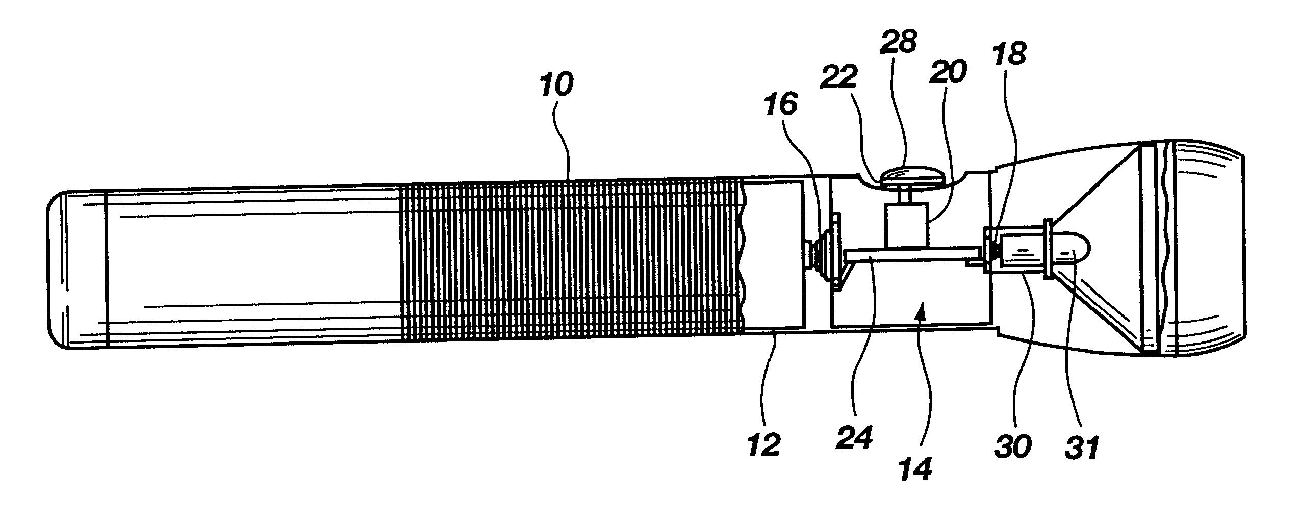
Referring now to FIG. 1, FIG. 1 shows a flashlight made in accordance with the principles of the present invention. This specific illustrative embodiment will be used to explain the principles of the present invention, but it will be understood that the scope of the present invention extends beyond flashlights of th...


PUM


Abstract

A flashlight with unique flashlight electrical connections, including a switch structure featuring a switch requiring a small amount of force, and a short stroke distance to actuate, attached to a member on which a circuit adding additional functions to the flashlight may be located. The member has conductive springs attached to either end that are used to complete the electrical circuit with the battery and the lamp, while their compressive force is absorbed by a housing protecting the switch structure. A conductive strip is used to improve the conductivity of the circuit in a metal flashlight which has been provided with an electrically resistive protective coating.

Description

1. The Field of the Invention.The present invention relates generally to portable illumination devices, and more particularly, but not entirely, to flashlights with enhanced functionality and reliability.2. Description of Background Art.Flashlights and other portable illumination devices are very useful devices that include an illumination source as part of an electrical circuit incorporating one or more batteries (to supply current to the illumination source) and a switch to complete or interrupt the circuit. Typically, manually operated mechanical switches which have been designed for the mechanical sturdiness have been used as flashlight switches, such as the switch disclosed in U.S. Patent No. 4,286,311 (granted Aug.25, 1981 to Maglica), which is hereby incorporated by reference. The function of a switch in previously available flashlight has been limited to completing or interrupting the electrical circuit to the illumination source.The switch used in the '311 patent is a push-...

Claims


Application Information

Patent Timeline
Patent Type & Authority Patents(United States)
IPC IPC(8): F21V23/04F21L4/00
CPCF21L4/005F21L4/027F21V23/0414F21L4/00F21L4/02Y10S362/802F21Y2101/02F21V23/009F21Y2115/10F21V23/0464F21V33/00
Inventor KOCH, GREG W.BANGERTER, BRUCE K.COLLIER, KEVIN E.STEINICKE, DARRELL B.
Owner MAG INSTR INC
Why Eureka
Try Eureka