Low dielectric constant materials and their production and use

a dielectric constant and low technology, applied in the field of low dielectric constant materials and their production and use, can solve the problems of poor heat resistance, increased f content of higher moisture absorption, and increasing the problem of signal delay, and achieve the effect of low moisture absorption

Inactive Publication Date: 2003-07-08
NIPPON STEEL CORP
View PDF11 Cites 30 Cited by
  • Summary
  • Abstract
  • Description
  • Claims
  • Application Information

AI Technical Summary

Benefits of technology

It is an object of the present invention to provide silica-based materials with low moisture absorption and a low dielectric constant, which can be applied for semiconductor elements and electrical circuit parts.

Problems solved by technology

With higher speeds and higher integration of LSI elements, signal delays are becoming an ever more serious problem.
The relative dielectric constant of SiOF reduces to about 3.3 as the F content increases, but higher moisture absorption with greater F content has been a problem.
Organic materials are low dielectric constant materials with relative dielectric constants of down to about 2.2, but their problems include poor heat resistance and low adhesion to substrates.
This film, however, has an increase of about 13% in the dielectric constant due to moisture absorption in air, while the introduced pores are also large so that only an average of 2 pores are present in a gap of 0.18 .mu.m between wiring, and thus film strength is therefore a problem.
However, the xerogel not only has a complicated fabrication process but strict control is necessary for each step in the process, and therefore lack of reproducibility for actual device fabrication is thought to be one of its drawbacks.
Since the annealing temperature for metal wiring in LSI processes is said to be 450.degree. C., this film would be expected to pose a problem when applied to such processes.

Method used


Image

  • Low dielectric constant materials and their production and use
  • Low dielectric constant materials and their production and use
  • Low dielectric constant materials and their production and use

Examples


example 2

Tetraethyl orthotitanate that had been reacted beforehand with ethyl acetoacetate, and methyltriethoxysilane and isobutyltriethoxysilane were mixed in a molar ratio of 1:1:5 in an ethanol solvent. After mixing, the mixture was hydrolyzed in a 10-fold molar amount of water with respect to the tetraethyl orthotitanate. This adjusted solution was spin-coated onto an Si wafer bearing platinum as a lower electrode for electric capacity measurement and onto an Si wafer for FT-IR measurement to form films thereon, after which they were dried for one minute each on hot plates set to temperatures of 70.degree. C., 150.degree. C. and 200.degree. C., in that order. Heat treatment was then carried out for 50 minutes at 450.degree. C. in a nitrogen atmosphere using an infrared furnace.

The FT-IR spectra revealed a structure with methyl groups and isobutyl groups in each SiO.sub.2 film prior to the heat treatment at 450.degree. C., but after the heat treatment showed a structure wherein the isobut...

examples 3-6

were fabricated with dimethyldiethoxysilane and the metal alkoxides listed in Table 2 as the starting materials. The ratio of the metal alkoxide to the dimethyldiethoxysilane was 1:10 in Example 3, 1:5 in Example 4, 1:10 in Example 5 and 1:20 in Example 6. These were stirred in an ethanol solvent, and a solution of water in ethanol was added for hydrolysis to prepare a sol. The resulting sol was poured into an aluminum dish and subjected to two-stage heat treatment at 70.degree. C. and 150.degree. C. to fabricate a bulk material. The dynamic viscoelasticity of the bulk material was measured under conditions of room temperature, 110 Hz frequency to determine the storage elastic modulus. An electrode was also connected to both sides of the bulk material to measure the dielectric constant at a frequency of 1 MHz.

Comparative Examples 2-5 were fabricated with a siloxane polymer represented by HO--[Si(CH.sub.3).sub.2 --O].sub.40 --H and the metal alkoxides listed in Table 2 as the startin...

examples 1-6

Calculation Examples 1-6 and Calculation Example 7 are examples where the dielectric constants of materials were calculated according to Equation 1, based on the polarizabilities of the model molecules shown in Table 3.

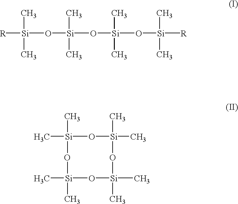
The proportion of the end-containing portions to end-free portions (for example, ring structures) among all of the polymer chains composing each material is designated as x:(1-x), (0.ltoreq.x.ltoreq.1). The proportion of molecules with end structures of --O--Si(CH.sub.3).sub.2 R (R is a group other than OH) to those with -O--Si(CH.sub.3).sub.2 OH is designated as y:(1-y), (0.ltoreq.y.ltoreq.1). Thus, Equation 1 is represented by: ##EQU3##

Here, .alpha..sub.R is the polarizability of linear molecules wherein the end groups R shown in FIG. 8 are not OH, .alpha..sub.OH is the polarizability particularly where the end groups are OH, .alpha.' is the polarizability of the ringed molecules shown in FIG. 8, and W.sub.R, W.sub.OH and W' are the molecular weights of their model ...


PUM

PropertyMeasurementUnit
sizeaaaaaaaaaa
molar ratioaaaaaaaaaa

Abstract

Silica-based low dielectric constant materials having three-dimensional network structures containing siloxane backbones which comprise SiO4 tetrahedron structural units, as well as their production and use. The materials can be applied as interlayer dielectrics for semiconductor elements and the like.

Description

The present invention relates to low dielectric constant materials such as insulating films (dielectrics) used between LSI element layers, etc., and to their production and use.With higher speeds and higher integration of LSI elements, signal delays are becoming an ever more serious problem. Signal delays are related to the product of the wiring resistance R and the capacity C between the wirings and between layers, and an effective means of minimizing delays involves lowering the wiring resistance while also reducing the relative dielectric constant of the interlayer dielectrics. By the year 2001, it is said that higher integration will result in wiring spacings of about 0.18 .mu.m, thus requiring materials with a relative dielectric constant of less than 2.5.Previously known methods form films as interlayer dielectrics by a spin-on-glass (SOG) process using sols prepared by hydrolyzing tetraalkoxysilanes. However, the molecular structures of materials fabricated in this fashion ha...

Claims


Application Information

Patent Timeline
Patent Type & Authority Patents(United States)
IPC IPC(8): C09D183/04C09D183/14H01L21/02H01L21/312
CPCC09D183/04C09D183/14H01L21/02126H01L21/02203H01L21/02216H01L21/02282H01L21/3122H01L21/3124Y10T428/249969Y10T428/249978Y10T428/249979
Inventor YAMADA, NORIKOTAKAHASHI, TORUSAKON, TADASHIMATSUZAKI, YOICHINOGAMI, ATSUSHIKATAYAMA, SHINGOSHIINA, IKUKO
Owner NIPPON STEEL CORP
Why Eureka
Try Eureka