Optical sensing devices

a technology of optical sensing and sensors, applied in the direction of converting sensor output, photometry, instruments, etc., can solve the problem of frequent calibration or "retraining" of sensors

Inactive Publication Date: 2003-07-08
INSTITUT NATIONAL D'OPTIQUE
View PDF5 Cites 29 Cited by
  • Summary
  • Abstract
  • Description
  • Claims
  • Application Information

AI Technical Summary

Problems solved by technology

Another major drawback experienced by these devices is sensor drift, which creates the necessity for frequent calibration or "retraining" of the sensors.

Method used


Image

  • Optical sensing devices
  • Optical sensing devices
  • Optical sensing devices

Examples


Embodiment Construction

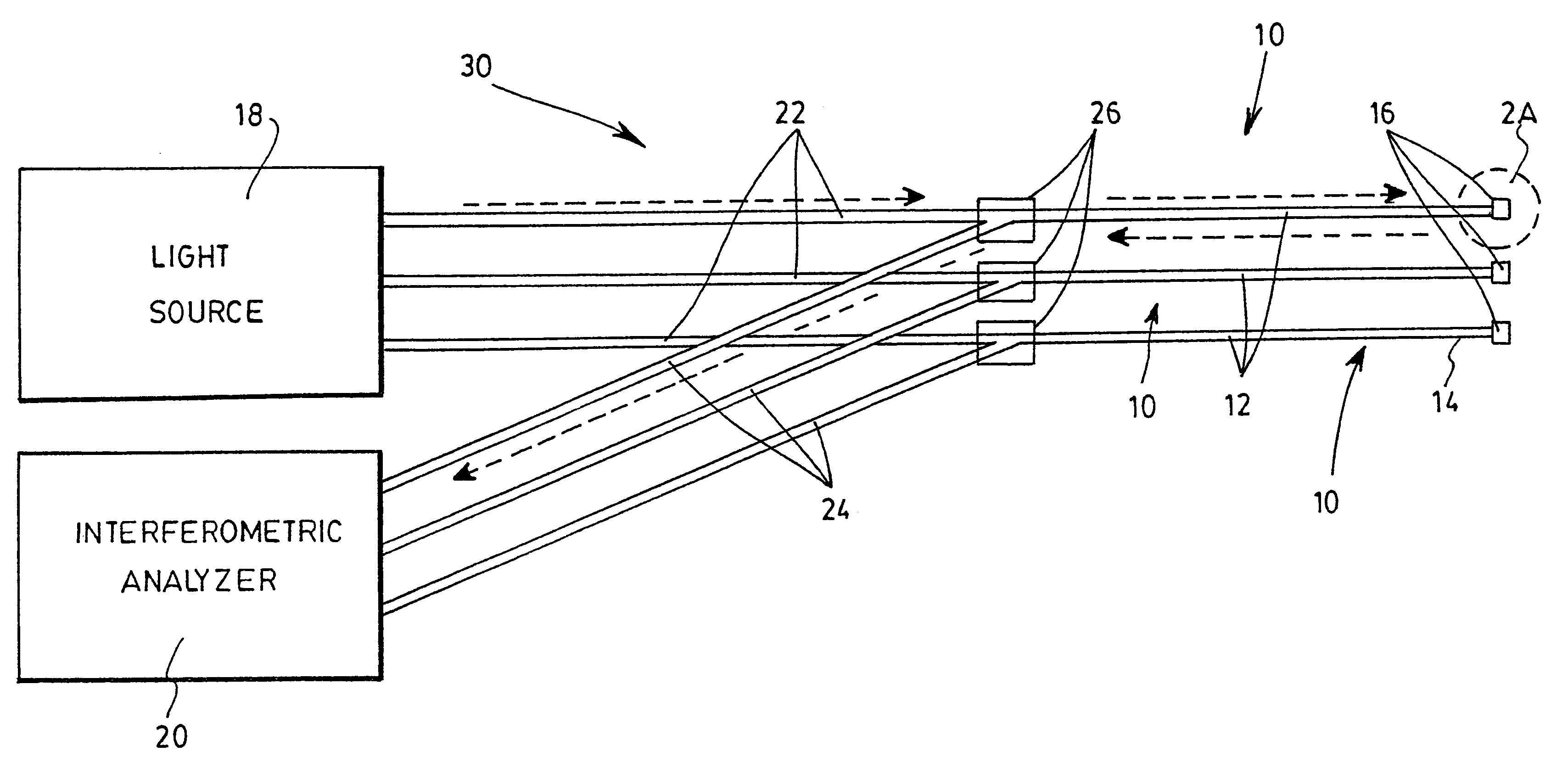
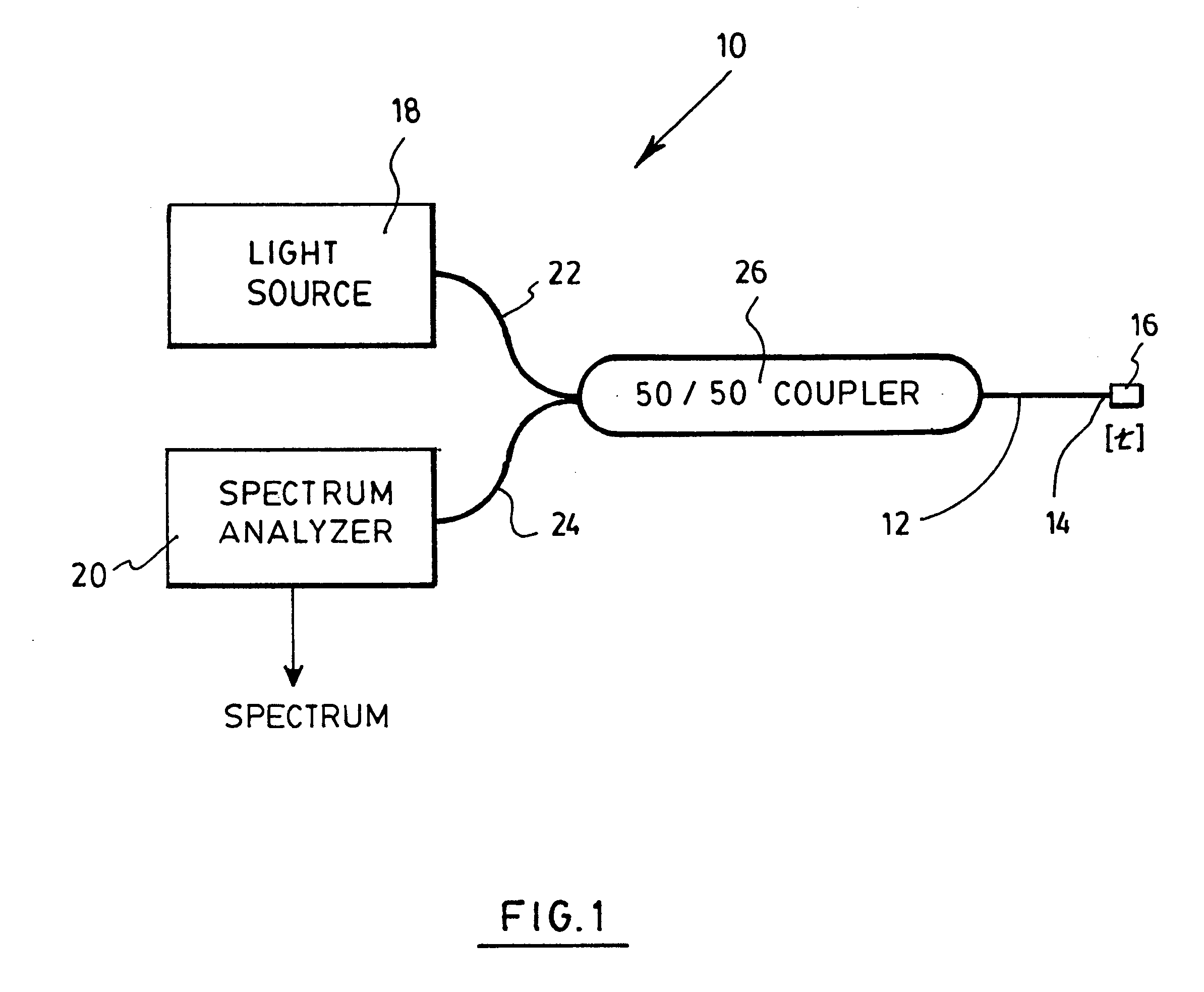
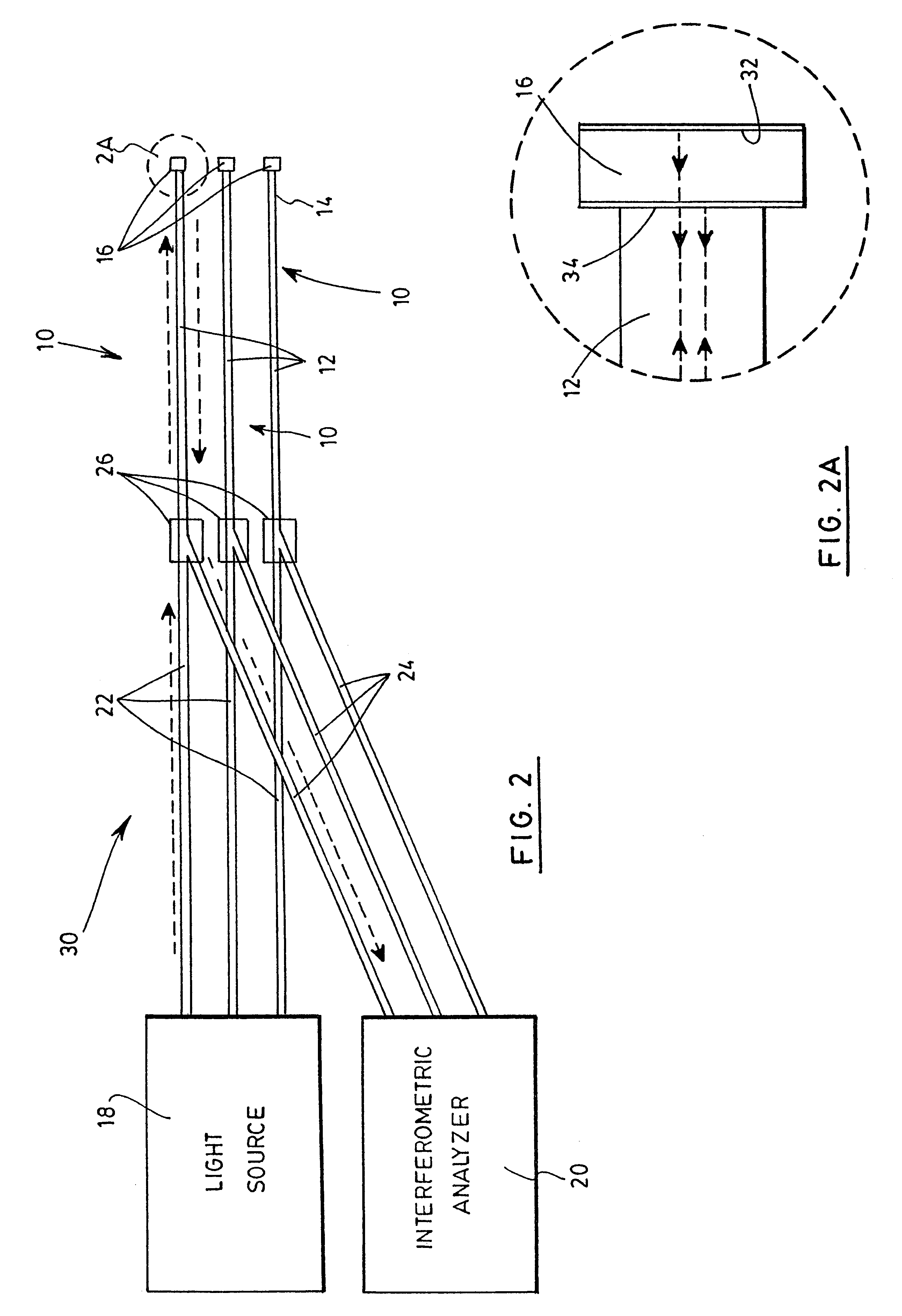
With reference to FIG. 1, there is shown an optical sensor 10 for detecting a substance in a solution in accordance with a first preferred embodiment of the invention.

The sensor 10 first includes an optical fiber 12, which could be a typical silica fiber or be made of any other appropriate material. The fiber 12 has a free extremity 14, which has been cut along the cross section of the fiber 12 so as to define a plane normal to its longitudinal axis. A polymer layer 16 is deposited on the free extremity 14, and extends in this normal plane. The polymer layer 16 has a thickness t related to substance to be detected when exposed thereto, as will be further explained below. Any number of polymeric materials may be used depending on the desired-sensibility of the device. The same polymers as those used for electronic noses may equally be chosen for the present invention. Example of such polymers include polydimethylsiloxane (PDMS), polyoctylmethylsiloxane (POMS), poly(isopropylcarboxyli...


PUM

PropertyMeasurementUnit
thicknessaaaaaaaaaa
spectrum analyzeraaaaaaaaaa
thicknessesaaaaaaaaaa

Abstract

An optical sensor is provided. The sensor includes an optical fiber having a free extremity on which a polymer layer is deposited normal to the longitudinal axis. A light source injects a analytical light beam in the fiber, which is reflected by the polymer layer. The reflected beam is analyzed by a spectrum analyzer, which determines the thickness of the polymer layer based on the Fabry-Perot effect. This thickness is related to a substance to be detected. An optical nose made from a plurality of such sensors is also provided, and may be used to detected a variety of substances.

Description

The present invention relates to optical devices for sensing substances in a solution, and more particularly concerns an optical sensor, an optical nose and a method of making the latter."Smell-detectors" or "electronic noses" are substance detecting devices based on a technique in full expansion which uses the absorption by polymeric membranes of analytes present in fluids. The absorption of the analytes by the polymeric membranes generates an alteration of its physical properties, such as density, thickness, refractive index, resistivity, etc.Electronic techniques for measuring these alterations of the properties of the membrane are well documented. For example, the product named "Cyranose 320" (trademark) from the company Cyrano Sciences Inc. is based on such a technique. Typically, an electronic nose is composed of many sensors made from different polymers, each having its own reaction to the presence of a given substance. Electronic noses generally measure the change in resisti...

Claims


Application Information

Patent Timeline
Patent Type & Authority Patents(United States)
IPC IPC(8): G01B11/06G01D5/26G01N21/77
CPCG01B11/06G01D5/268G01N2021/7723G01N2021/7773G01N2021/7779
Inventor PAINCHAUD, YVESLEVESQUE, MARCCARON, SERGEGALARNEAU, PIERRE
Owner INSTITUT NATIONAL D'OPTIQUE
Why Eureka
Try Eureka