
Top water lure with highly active propeller

a propeller and high-active technology, applied in the field of top water lures, can solve the problems of limited activity created by short pulls on the line, defeating the purpose of simulating wounded fish, and not being able to travel fast, and achieve the effect of adjusting the noise and churning, and reducing the difficulty of fishing

Inactive Publication Date: 2003-07-15
SABINE KENNETH P
View PDF18 Cites 17 Cited by
  • Summary
  • Abstract
  • Description
  • Claims
  • Application Information

AI Technical Summary

Benefits of technology

The propeller design enhances the lure's visibility and attractiveness to fish by creating a larger wake and more bubbles, reduces entanglement, and maintains rotation at slow speeds, providing a broader range of noise and water responses.

Problems solved by technology

While this lure has been successful, it has several drawbacks.
Additionally, the amount of activity which can be created with short pulls on the line is very limited.
In fact, to provide the tiniest of wakes, it is necessary to provide a rip (rapid pull) of at least one foot, at unnaturally high speed, thereby defeating the purpose of simulating a wounded fish, which would not travel fast.

Method used


Image

  • Top water lure with highly active propeller
  • Top water lure with highly active propeller
  • Top water lure with highly active propeller

Examples


Embodiment Construction

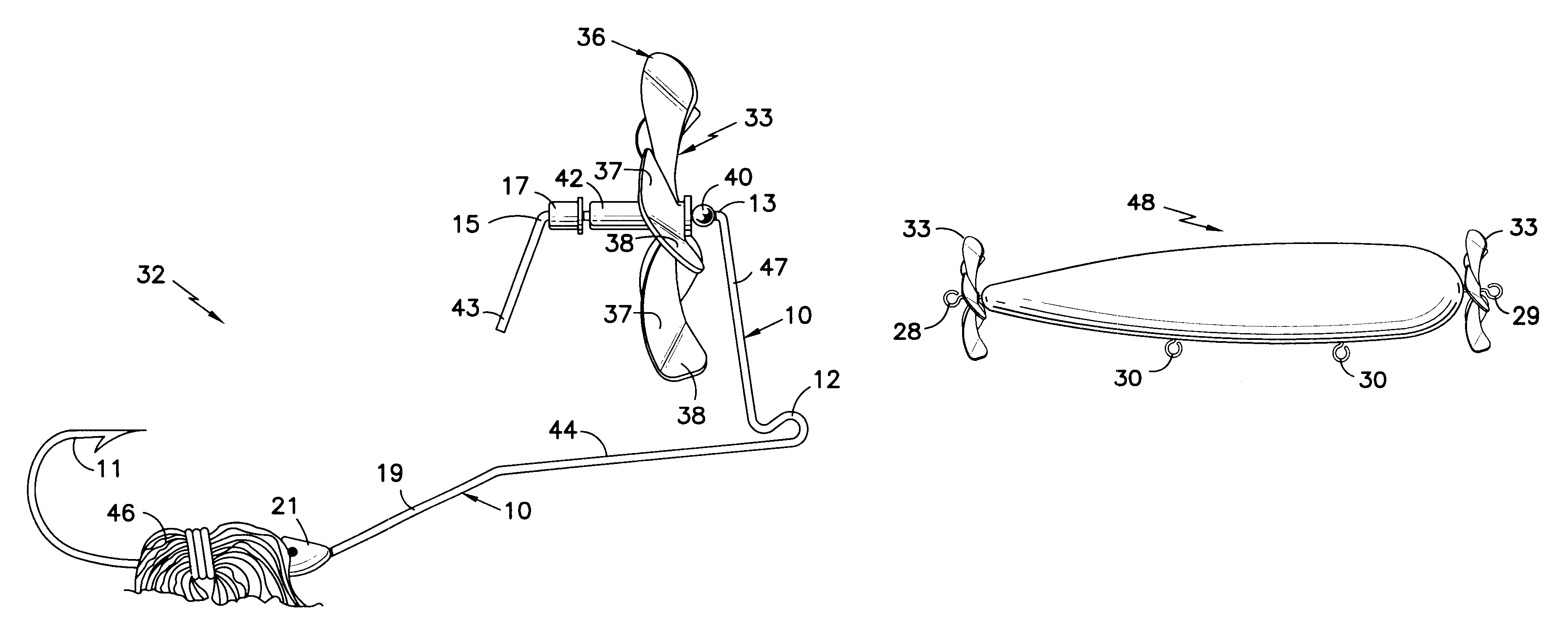
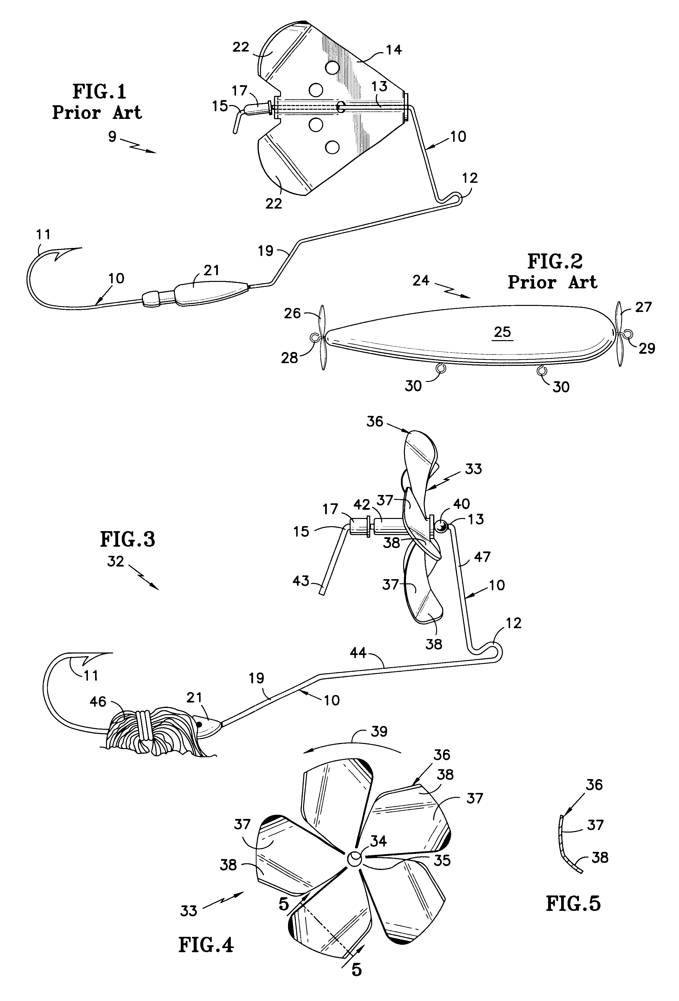
Referring to FIGS. 3-5, a propeller 33 has a central hole 34 which defines its axis of rotation, the material 35 between the hole 34 and each of the individual blades 36 comprises a hub. Each of the blades 36 has a first portion 37 proximal to the hub 35 which has a first degree of pitch and a distal portion 38 having a degree of pitch which is greater than the degree of pitch of the proximal portion 37. The pitch in each blade is in the same direction as the pitch of each other blade, but it need not be the same degree of pitch from one blade to the next. In the propeller illustrated in FIGS. 3 and 4, the pitch is such as to cause rotation of the blade in the direction shown by the arrow 39. The portions 37, 38 of each blade may include an angle on the order of 120.degree., although this can vary significantly. A hollow bead 40 is used as a spacer so that the shank 10 does not interfere with the blades 36. However, if there is a relatively low pitch or significant rake in the blade...


PUM


Abstract

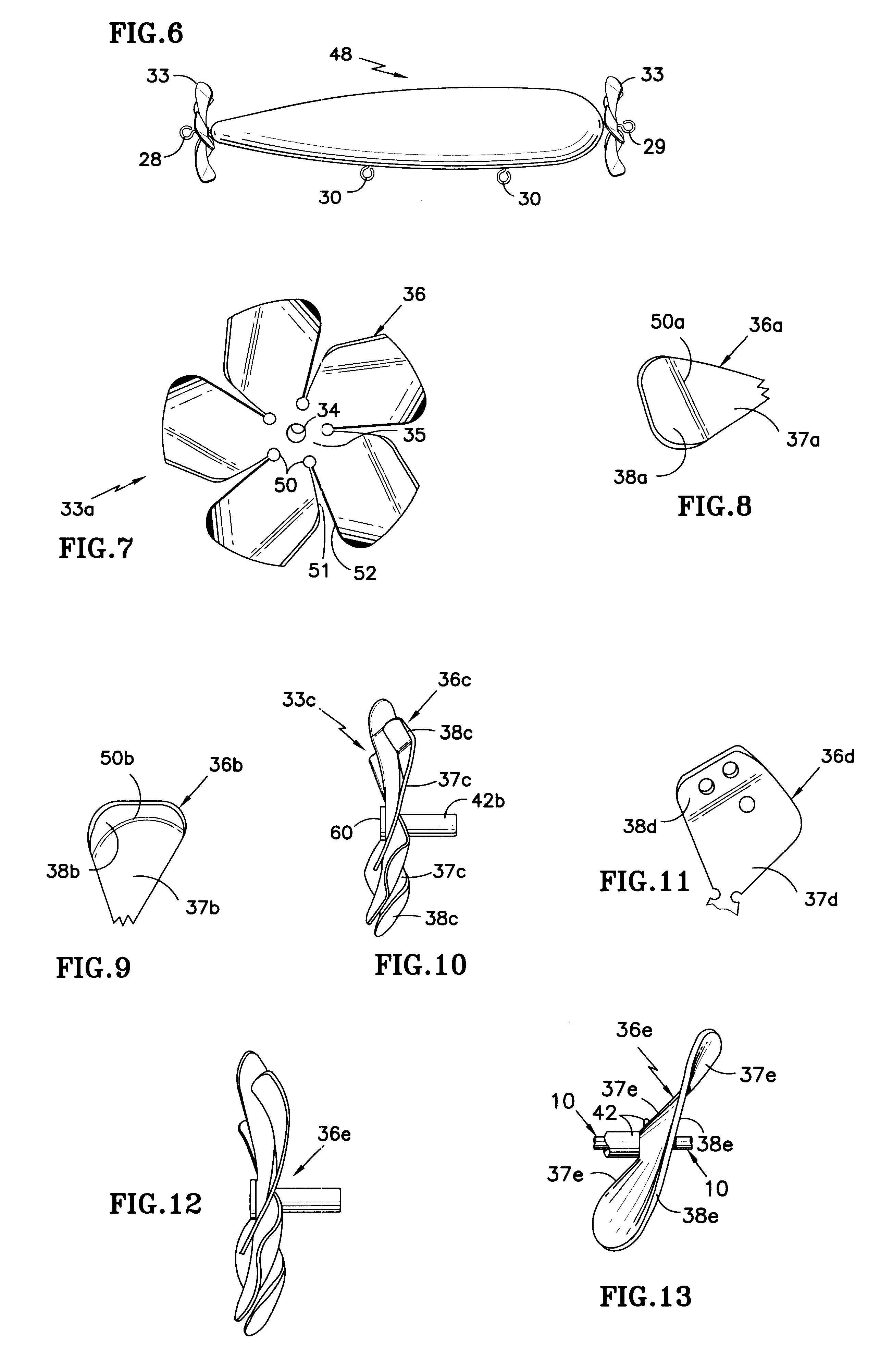
A propeller 33 is disposed on a bearing collar 42 to rotate about a shaft 10 of a lure 32. The propeller has a plurality of blades 36, each having a proximal portion 37 with a first degree of pitch and a distal portion 38 having a second degree of pitch which is different than said first degree of pitch. The blades may have distal ends which have the same direction of pitch as the proximal ends, or distal ends which have pitch opposite to that of the proximal ends. The blades may have straight bends or curved bends between the proximal and distal portions, and each blade may comprise a single, smoothly curvilinear surface. The blades may have one or more holes of various sizes in one or more blades of each propeller, either in the distal portion or the proximal portion of the blades. One or more propellers may be mounted on buzz baits, top water lures including plugs, and on other lures.

Description

This invention relates to top water lures, such as buzz baits and top water plugs, having one or more propellers disposed thereon for creating noise, splashing water and a wake of bubbles.In FIG. 1, a fishing lure 9 commonly referred to as a "buzz bait" or "buzzer" of a conventional, "safety pin" design, has a shaft 10 with a rearward portion formed into a fish hook 11, a medial portion formed into an eye 12 for attaching a fish line to draw the lure through the water, and a bridge portion 13 upon which a propeller 14 is disposed to rotate, the rearward tip 15 of the shaft being bent so as to retain the propeller 14 thereon. A rivet bearing 17 acts as a thrust bearing as the propeller 14 is driven rearwardly on the bridge portion 13 when the lure is drawn through the water to the right as seen in FIG. 1. The shaft may have a kink 19 in it so as to place a weight 21 disposed thereon below the line of motive force, through the eyelet 12, thereby to provide vertical stability to the lu...

Claims


Application Information

Patent Timeline
Patent Type & Authority Patents(United States)
IPC IPC(8): A01K85/00A01K85/12
CPCA01K85/00A01K85/12
Inventor SABINE, KENNETH P.
Owner SABINE KENNETH P
Learn More