Method and apparatus for pulsed discharge forming of a dish from a planar plate

a technology of a planar plate and a plate is applied in the field of apparatus for forming a generally planar metal plate into a dish, which can solve the problems of workpiece deformation, high energy consumption, complicated and costly installation,

Inactive Publication Date: 2003-07-15
INFINITY IP COMMERCIALIZATION ISRAEL LTD
View PDF19 Cites 62 Cited by
  • Summary
  • Abstract
  • Description
  • Claims
  • Application Information

AI Technical Summary

Benefits of technology

As a result of the pulsed discharge of current through the pairs of electric discharge members, portions of the metal plate are induced into a very rapid movement giving rise to either forming or shearing. Where the rapidly moving metal surface moves into a depression, any gasses which remain in the depression can resist the movement and prevent the obtaining of the desired shape defined by the mold, which is particularly problematic in the case of a large depression, e.g. in the case of the central concave depression of the embodiment mentioned above. Accordingly, in accordance with one preferred embodiment, gas ducts are provided to allow egression of gasses from one or more depressions in the mold. Preferably, such ducts are connected to a vacuum source, whereby all the gasses are removed prior to the generation of the pulsed magnetic force.

Problems solved by technology

However, such a process is applicable in certain specific cases and in addition requires the expense of a large amount of energy and complicated and costly installations for heating and cooling.
Such pressing methods require a very costly and large installations required for achieving the necessary pressure for attaining the desired final object.
The resulting eddy currents that are induced in the workpiece yields a magnetic repulsion between the workpiece and the forming coil, which cause the workpiece to deform.

Method used


Image

  • Method and apparatus for pulsed discharge forming of a dish from a planar plate
  • Method and apparatus for pulsed discharge forming of a dish from a planar plate
  • Method and apparatus for pulsed discharge forming of a dish from a planar plate

Examples


Embodiment Construction

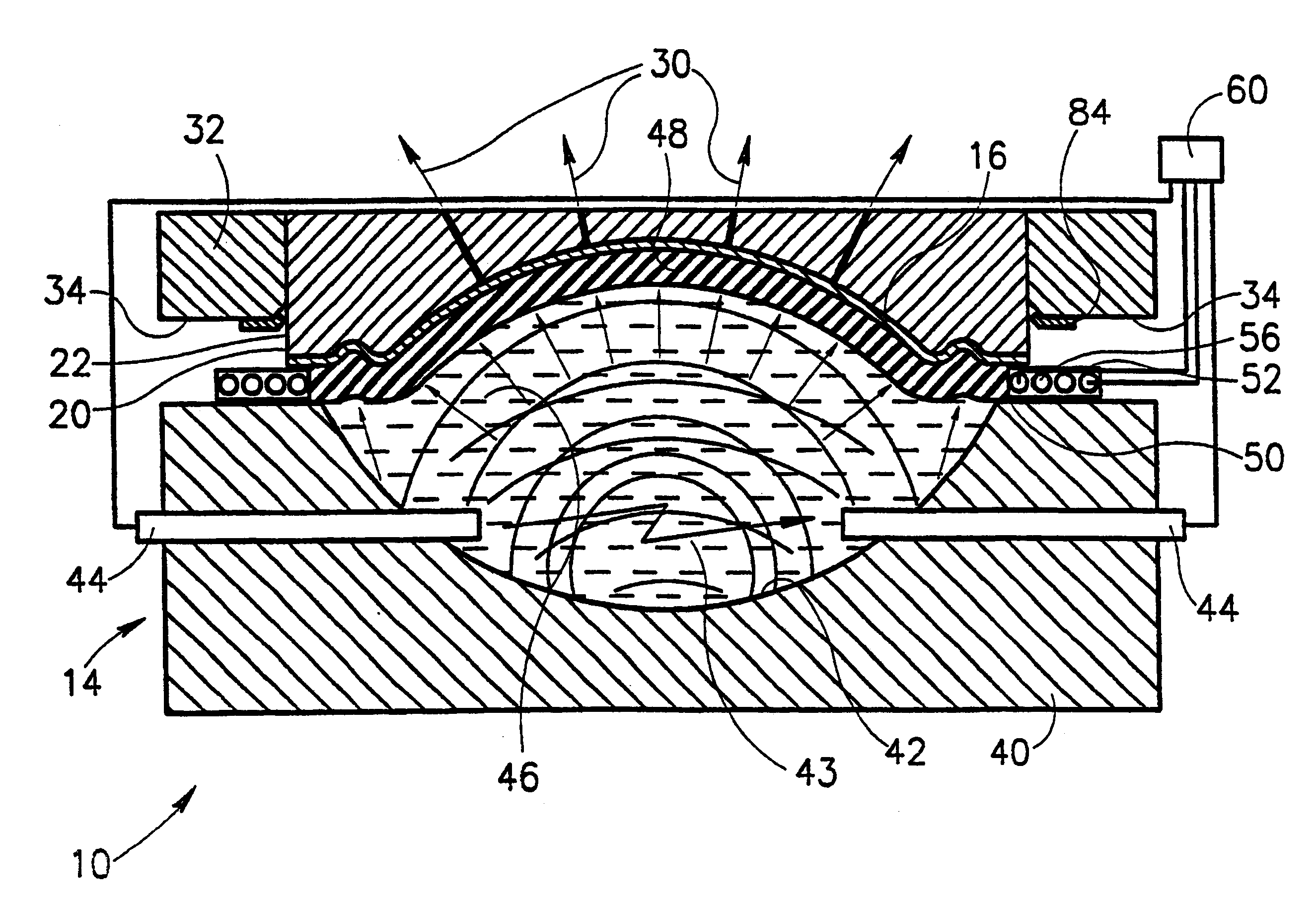
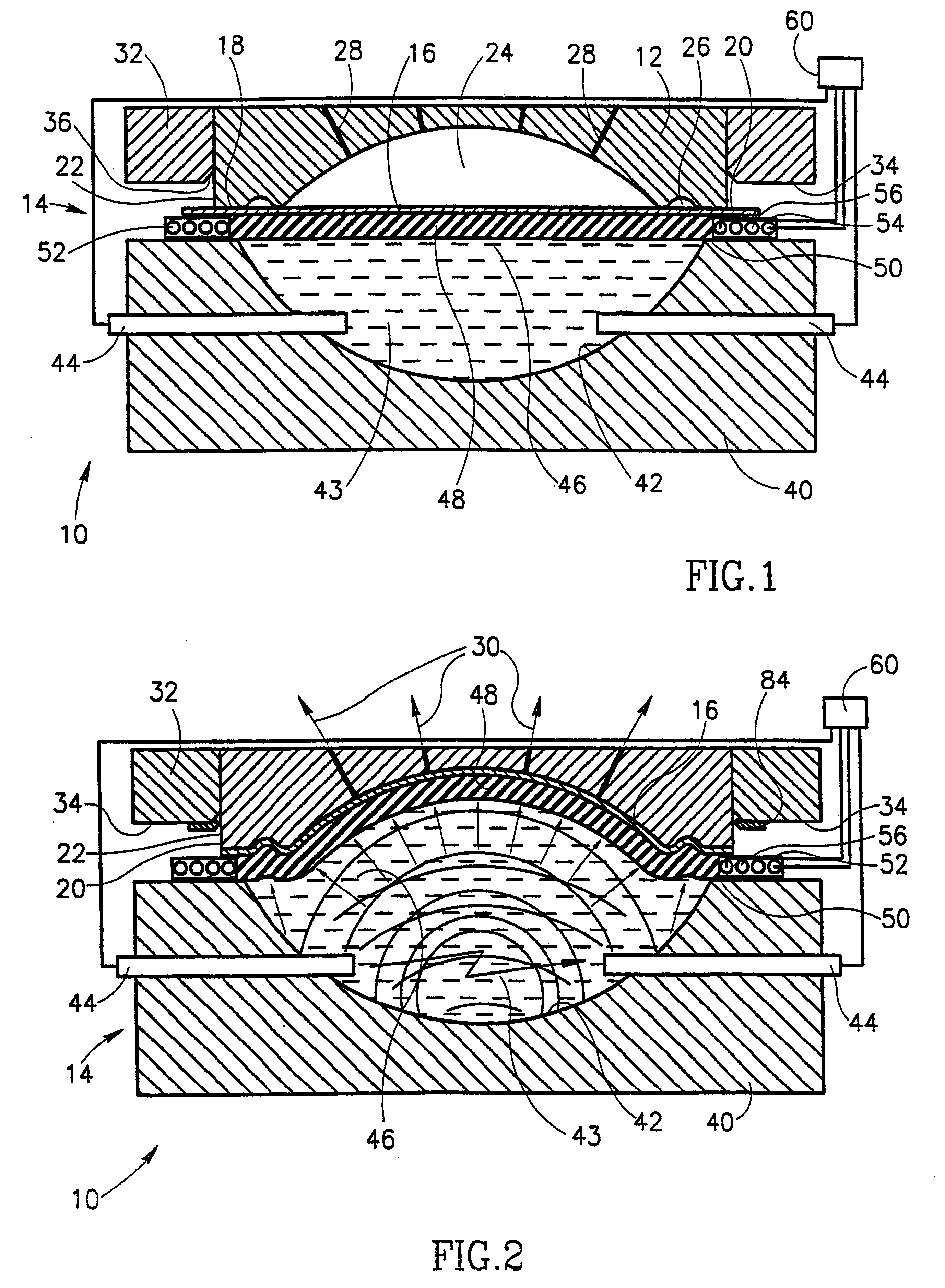
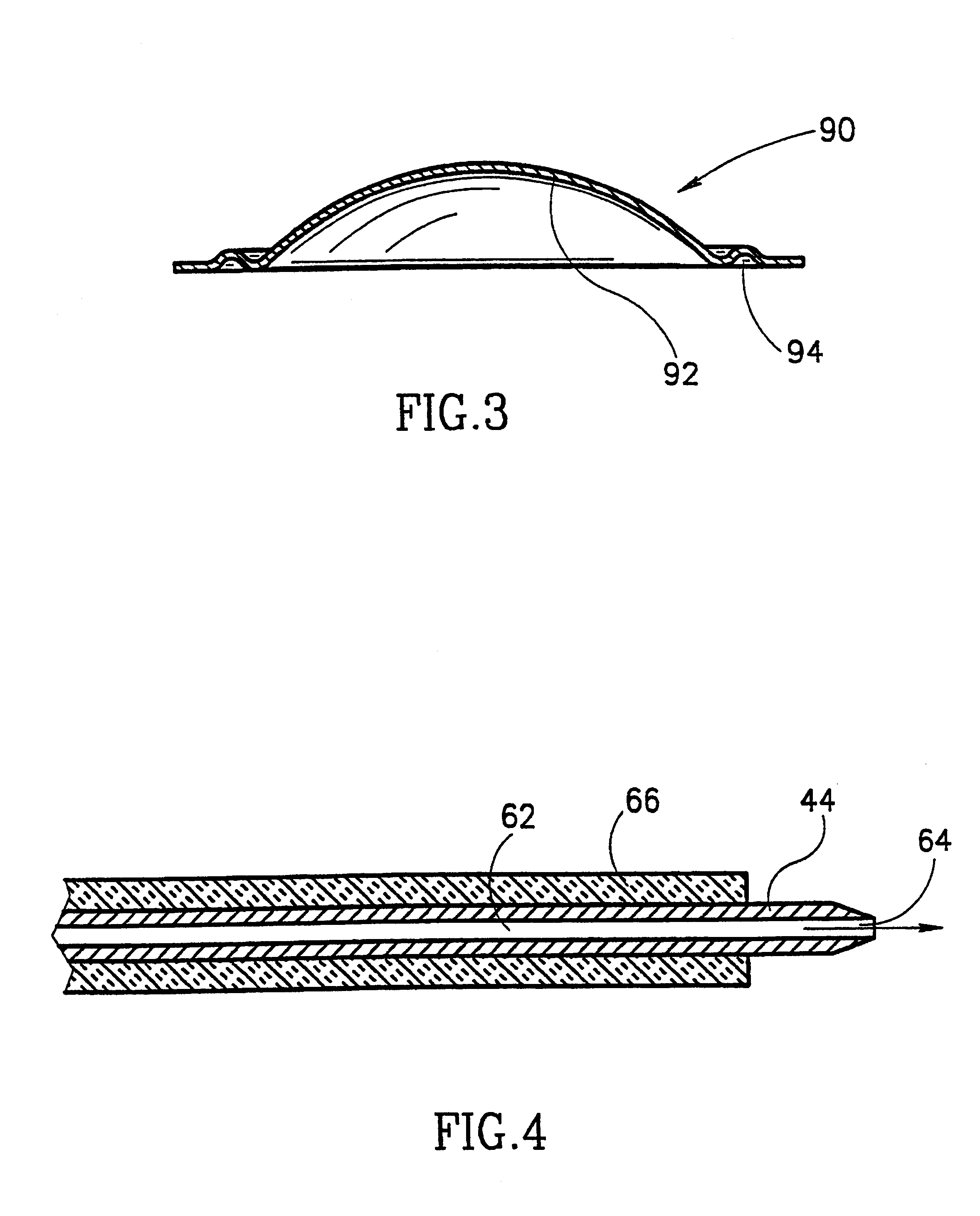
Reference is first being made to FIG. 1 showing an apparatus generally designated 10 comprising a mold 12 and a force generating assembly 14 holding between them a metal plate 16.

Mold 12 has a forming surface 18 of a generally circular shape with edges 20 defined by upright walls 22 with a central dome-shaped depression 24 and an annular groove 26. As will be appreciated, the specific shape of the mold which defines the shape of the dish to be formed in the apparatus is an example only and it may assume also a variety of other shapes. By way of illustration, the mold may have an overall rectangular shape, may have different kinds of depressions for forming dishes with different three-dimensional patterns, etc. Thus the specific illustrated embodiment does not derogate from the generality of the invention as defined herein.

Formed in mold 12 are a plurality of ducts 28 leading from depression 24 to a vacuum source (not shown) which draws gas from the depression (represented by arrows ...


PUM

PropertyMeasurementUnit
pressureaaaaaaaaaa
electric currentaaaaaaaaaa
electric dischargeaaaaaaaaaa

Abstract

An apparatus for forming a generally planar metal plate into a dish with a three-dimensional pattern is provided. The apparatus comprises a mold having a forming surface with a contour corresponding to said three-dimensional pattern, and having edges corresponding to boundaries of the dish, which edges are defined by side walls essentially perpendicular to the forming plane; a forming device comprising a fluid basin and pairs of electric discharge members within the fluid and having an opening facing the mold to allow transmission of a pressure wave from the fluid to the metal plate; and an electric discharge circuitry for discharging a short and intense electric current through the pairs of electric discharge members generating an electric spark or breakdown within the fluid to yield formation of plasma, vapor or both.

Description

The present invention is generally in the field of forming and provides an apparatus and method for such forming. More particularly, the present invention relates to such apparatus wherein the forming force is generated by a rapid discharge of an electric pulse.Metal objects can be formed to have a desired shape by a variety of processes. For example, metal in a liquid form, can be molded to have the desired final shape. However, such a process is applicable in certain specific cases and in addition requires the expense of a large amount of energy and complicated and costly installations for heating and cooling.Metal has some pliability and accordingly metalwork pieces of one shape can at times be formed to have another shape. For example, a metal plate can be formed and cut to have a wide variety of desired shapes by using a mechanical press. Such pressing methods require a very costly and large installations required for achieving the necessary pressure for attaining the desired f...

Claims


Application Information

Patent Timeline
Patent Type & Authority Patents(United States)
IPC IPC(8): B21D26/12B21D26/00
CPCB21D26/12Y10T29/49805Y10T29/49806
Inventor GAFRI, ORENLIVSHIZ, YURI
Owner INFINITY IP COMMERCIALIZATION ISRAEL LTD
Why Eureka
Try Eureka