Magnetic recording apparatus and integrated circuit for magnetic recording with a shaped waveform

a technology of integrated circuits and magnetic recording, which is applied in the direction of digital recording/reproduction, data recording, instruments, etc., can solve the problems of difficult to shorten the time needed for reversing the magnetic polarity, the rise or fall rate has not yet been so much improved, and the problem of conventional magnetic recording apparatuses still have problems to be solved

Inactive Publication Date: 2003-07-15
TOSHIBA STORAGE DEVICE CORP
View PDF6 Cites 6 Cited by
  • Summary
  • Abstract
  • Description
  • Claims
  • Application Information

AI Technical Summary

Problems solved by technology

However, such a conventional magnetic recording apparatus still has following problems to be solved.
A constant settling level of the recording signal (recording current) makes it difficult to shorten the time needed for reversing the magnetic polarity (a rising time and a falling time).
In contrast to the recent remarkable improvement in the transfer rate of the recording signal, a rising or a falling rate has not yet been improved so much

Method used


Image

  • Magnetic recording apparatus and integrated circuit for magnetic recording with a shaped waveform
  • Magnetic recording apparatus and integrated circuit for magnetic recording with a shaped waveform
  • Magnetic recording apparatus and integrated circuit for magnetic recording with a shaped waveform

Examples


first embodiment

FIG. 4 shows a waveform of a recording current as shaped by the waveform shaping section of the magnetic recording apparatus of the FIG. 5 shows a waveform as shaped by the waveform shaping section of the present invention, and a comparative waveform input to the recording head of the conventional magnetic recording apparatus.

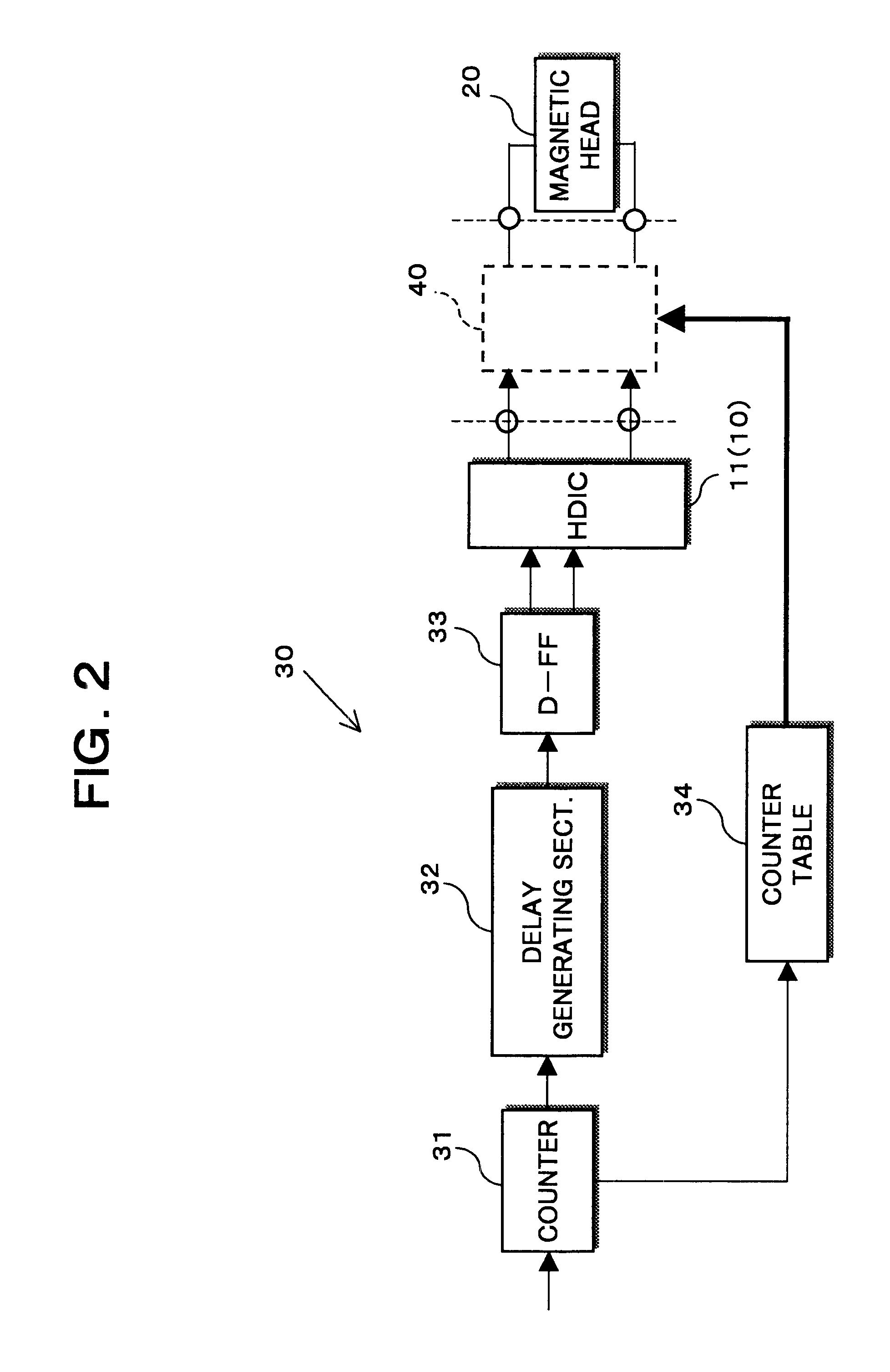
As shown in FIG. 4, the waveform of the recording current as shaped by the waveform shaping section 40a is such that a current value of the recording current infinitely approaches the magnetization inverse level (C of FIG. 4), which is previously obtained as a predetermined value, while keeping in a level exceeding the predetermined value during a period of the detected number of clocks by the counter 31, or a period corresponding to the data length (B of FIG. 4).

With reference to FIG. 5, a comparison will now be made between a waveform as shaped by the waveform shaping section 40a and a waveform of a recording current as output by the HDIC 11. In FIG. 5, the ...

second embodiment

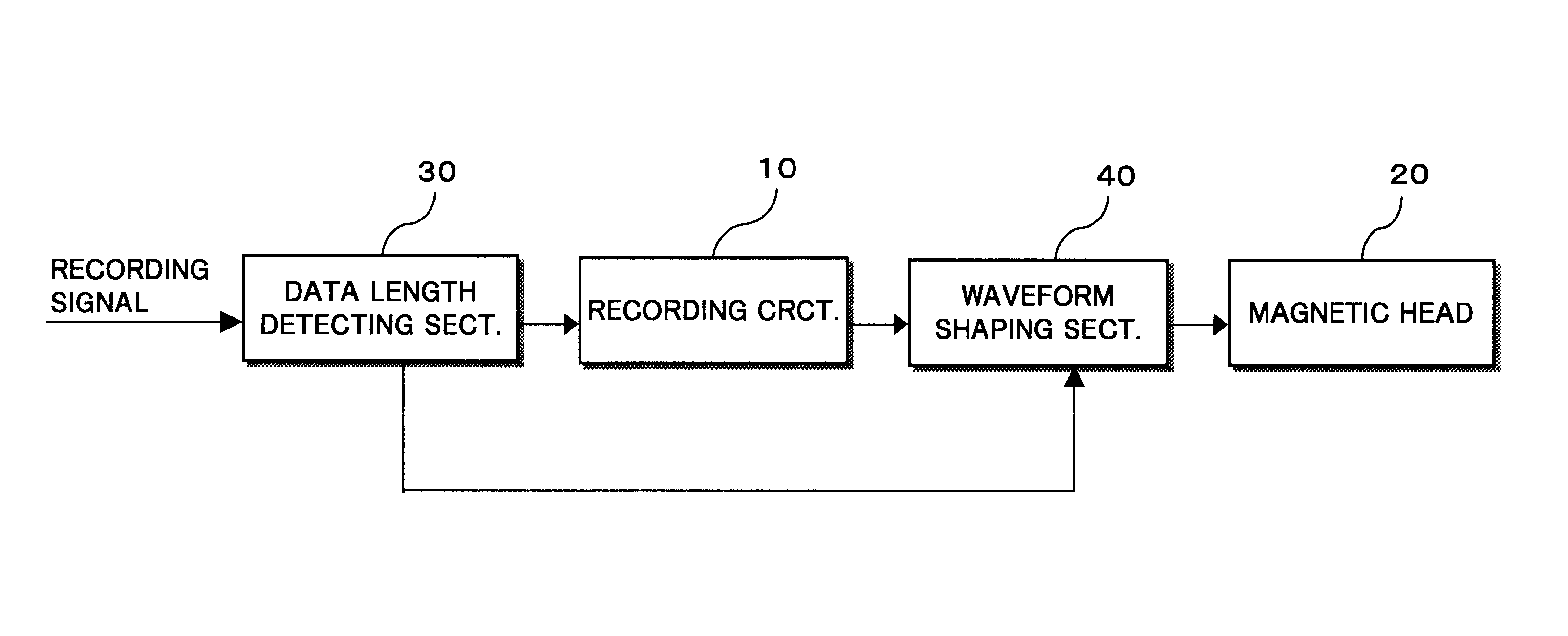
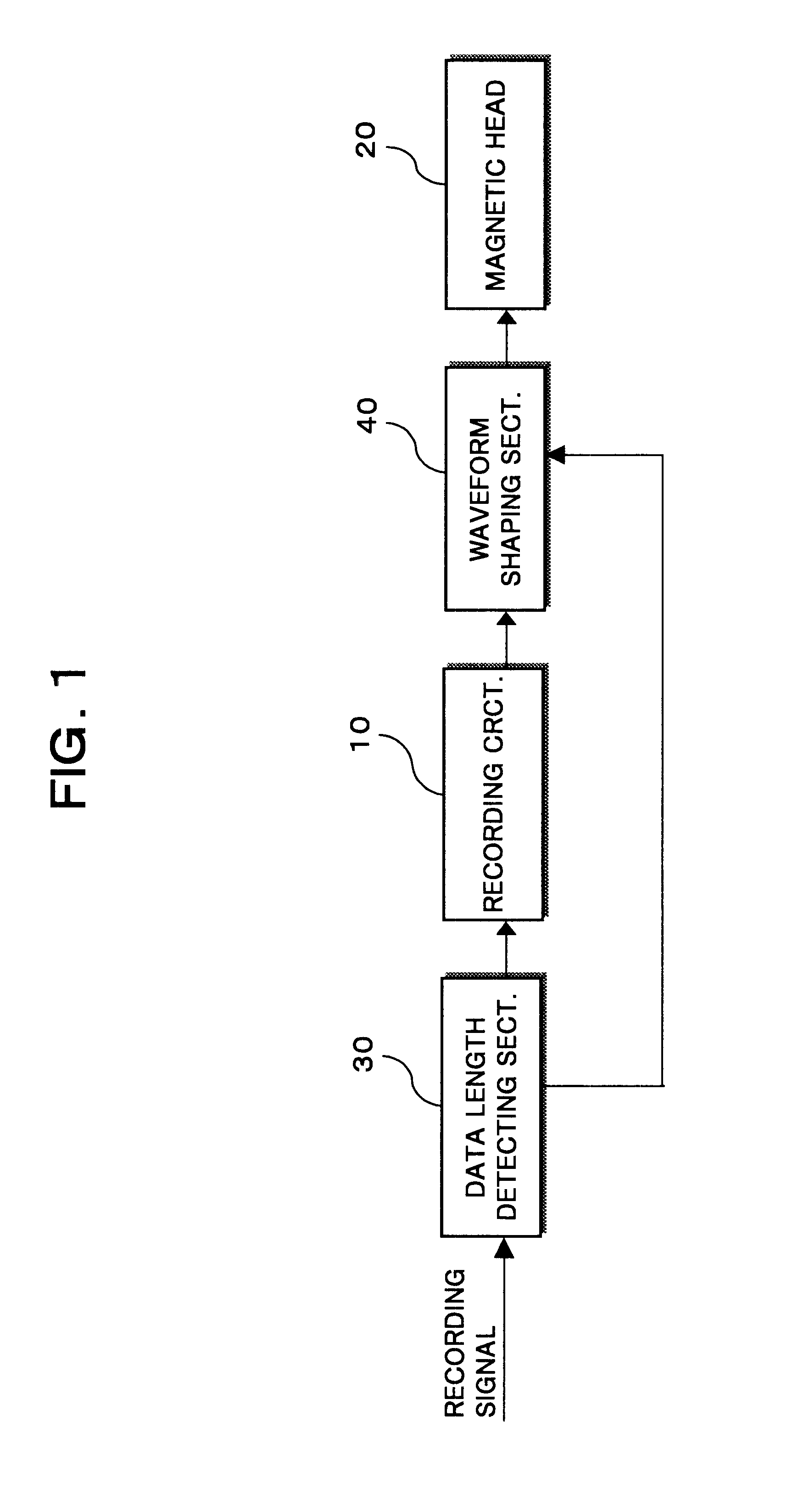
FIG. 12 shows a magnetic recording apparatus according to the present invention. The magnetic recording apparatus is equipped with a waveform shaping section 40' disposed upstream of the HDIC 11 (recording circuit 10). The waveform shaping section 40' shapes the waveform of the input recording signal in such a manner that the current value of the recording current infinitely approaches a predetermined value (the magnetization inverse level) while keeping in a level exceeding the last-named value throughout a period corresponding to a data length detected by the data length detecting section 30.

In the magnetic recording apparatus of FIG. 12, the waveform shaping section 40' shapes a recording signal into a sag-shaped waveform and then inputs the resulting recording signal into the recording circuit 10 with same results as mentioned above.

In the second embodiment, the waveform shaping section 40' may have any alternative form as of the waveform shaping sections 40a through 40f. Yet va...


PUM


Abstract

A magnetic recording apparatus equipped with a recording circuit for generating a recording current corresponding to an input recording signal, a magnetic head, operable in response to the generated recording current, for recording, in a magnetic recording medium, data corresponding to the input recording signal, and a waveform shaping section for shaping the generated recording current such that a current value of said recording current approximates to a predetermined value while keeping thereover throughout a period corresponding to the data length. Both the recording circuit and the waveform shaping section may be mounted in an integrated form on a single microchip. The result is that the input recording signal can be transferred at high speed as measures are provided to reduce both a rise time and a fall time of the recording current.

Description

1. Field of the InventionThe present invention relates to a magnetic recording apparatus and an integrated circuit for magnetic recording which are suitable for use in recording data in a magnetic recording medium, in the form of a disc, or a tape.2. Description of the Related ArtWhen data recording is carried out by a magnetic recording apparatus in common use, such as a magnetic disc device or a digital video tape recorder, onto a magnetic recording medium such as a magnetic disc or a magnetic tape, input data (recording signal) received from an upper apparatus or the like is amplified by an amplifier up to a level high enough to cause a flux reversal (hereinafter also called the inversion of magnetization) on the magnetic recording medium, and then recorded by a magnetic head onto the magnetic medium.At that time, the recording signal (recording current) amplified by the amplifier takes a square waveform whose magnetic polarity is repetitively reversed (positive or negative, or "...

Claims


Application Information

Patent Timeline
IPC IPC(8): G11B5/09G11B20/10G11B5/02G11B5/035G11B5/00
CPCG11B5/02G11B5/09G11B20/10009G11B5/035G11B2005/0013
Inventor YAMAGISHI, MICHINAGAUEHARA, YUJI
Owner TOSHIBA STORAGE DEVICE CORP
Why Eureka
Try Eureka