
Roasting device

A technology of a baking device and a conveying device, which is applied in the field of mechanical devices, can solve the problems of reducing economic benefits, large one-time investment, environmental pollution, etc., and achieve the effects of avoiding high temperature environment, stable and uniform heating, and high transmission speed.

Inactive Publication Date: 2016-06-01
无锡美悦电器有限公司
View PDF5 Cites 0 Cited by
  • Summary
  • Abstract
  • Description
  • Claims
  • Application Information

AI Technical Summary

Problems solved by technology

[0002] Wood baking is a very important process in the plate processing industry. The general wood baking devices include ovens that use firewood or coal as the direct heat source, ovens that use electric heating as the heat source, and ovens that use electric heating as the heat source. Although it is more advanced and intelligent, it is more convenient to use, but due to its large one-time investment and large power consumption during operation, the cost is too high
Therefore, ovens that use firewood or coal as a direct heat source are still widely used, but for ovens that use firewood or coal as a direct heat source, the high-temperature flue gas generated during combustion is directly discharged, and the heat It cannot be fully absorbed, the thermal efficiency is low, and a large amount of flue gas emissions will also cause certain pollution to the environment. Its thermal conductivity stability is relatively poor, and the temperature cannot be better controlled, resulting in easy damage to the baked board. Reduced economic benefits

Method used


Image

  • Roasting device

Examples


Embodiment Construction

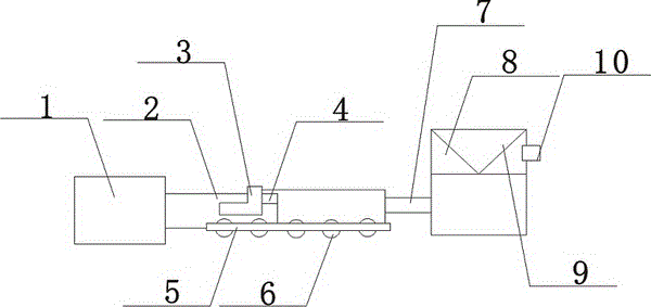
[0014] The present invention is described in further detail now in conjunction with accompanying drawing. These drawings are all simplified schematic diagrams, which only illustrate the basic structure of the present invention in a schematic manner, so they only show the configurations related to the present invention.

[0015] Such as figure 1 The preferred embodiment of the baking device of the present invention shown includes an oven body 1, a conveying device 2 is provided on the side of the oven body 1, the conveying device 2 and the oven body 1 are connected by a transmission belt, and a heating device is provided on the conveying device 2 3. The heating device 3 is fixedly connected to the conveying device 2. An adjustment mechanism 4 is provided on the side of the heating device 3. The adjustment mechanism 4 is connected to the heating device 3 through a built-in adjustment member. The conveying device 2 is provided with a slide rail 5 near the lower surface. A pulley...


PUM


Abstract

The invention discloses a drying device, which comprises a drying oven body, wherein a conveyor device is arranged on the side face of the drying oven body; the conveyor device and the drying oven body are connected through a transmission belt; a heating device is arranged on the conveyor device; the heating device and the conveyor device are fixedly connected; a regulating mechanism is arranged on the side face of the heating device and is connected with the heating device through a built-in regulating part; a slide rail is arranged on a part, close to the lower surface, of the conveyor device; a pulley is arranged on the slide rail; a transmission gear is arranged between the pulley and the slide rail; a connecting shaft is arranged on the side face of the conveyor device; one end of the connecting shaft extends in the conveyor device; the other end of the connecting shaft is connected with a hydraulic cylinder; a hydraulic groove is formed in the hydraulic cylinder; a heat transfer oil plate is also arranged in the hydraulic cylinder and is located in the hydraulic groove. The drying device is compact in structure, safe to use and convenient to install, and has the characteristics of high heat efficiency, stable and uniform heat supply, quick heat transfer speed and high transmission rate; people are positioned from being positioned under severe high temperature environment to a certain degree.

Description

technical field [0001] The invention relates to a mechanical device, in particular to a baking device. Background technique [0002] Wood baking is a very important process in the plate processing industry. The general wood baking devices include ovens that use firewood or coal as the direct heat source, ovens that use electric heating as the heat source, and ovens that use electric heating as the heat source. Although it is more advanced and intelligent, it is more convenient to use, but due to its large one-time investment and large power consumption during operation, the cost is too high. Therefore, ovens that use firewood or coal as a direct heat source are still widely used, but for ovens that use firewood or coal as a direct heat source, the high-temperature flue gas generated during combustion is directly discharged, and the heat It cannot be fully absorbed, the thermal efficiency is low, and a large amount of flue gas emissions will also cause certain pollution to t...

Claims


Application Information

Patent Timeline
Patent Type & Authority Patents(China)
IPC IPC(8): F26B15/02F26B23/10
Inventor 曾玥
Owner 无锡美悦电器有限公司
Learn More