Hold down toggle clamp

a toggle clamp and clamping technology, applied in the field of clamps, can solve the problems of reducing the life of the clamp, releasing the clamp, and increasing the wear and potential deformation of the clamping components

Inactive Publication Date: 2003-07-22
DELAWARE CAPITAL FORMATION INC
View PDF7 Cites 29 Cited by
  • Summary
  • Abstract
  • Description
  • Claims
  • Application Information

AI Technical Summary

Benefits of technology

Another object of the present invention is to provide a more robust hold down clamp.
Still a further advantage of the present invention is that the clamp eliminates pinch points by placing moving parts of the clamp within the handle mechanism.

Problems solved by technology

Further, prior art clamps create a holding force by passing the links of the toggle clamps to an over center position, the over center position subjects the links and the pivot points of the clamp to very high loads resulting in increase wear and potential deformation of the clamp components thereby reducing the life of the clamp.
There also have been problems with prior art clamps releasing due to vibration and other unforeseen forces during the use of the clamps.
Many of the prior art clamps also included several bends in the links and power arms of the clamp, thus reducing performance strength by amounts up to 30 to 40%.
Furthermore, clamps that include parts that have bends are not interchangeable and have to be put together in a certain manner, thus increasing the cost of labor of assembling the clamps.
This also increases the number of parts needed to build a specific number of the prior art clamps.

Method used


Image

  • Hold down toggle clamp
  • Hold down toggle clamp
  • Hold down toggle clamp

Examples


Embodiment Construction

)

The invention will now be described with reference to the drawings, where in like numerals in different drawing figures indicate like elements.

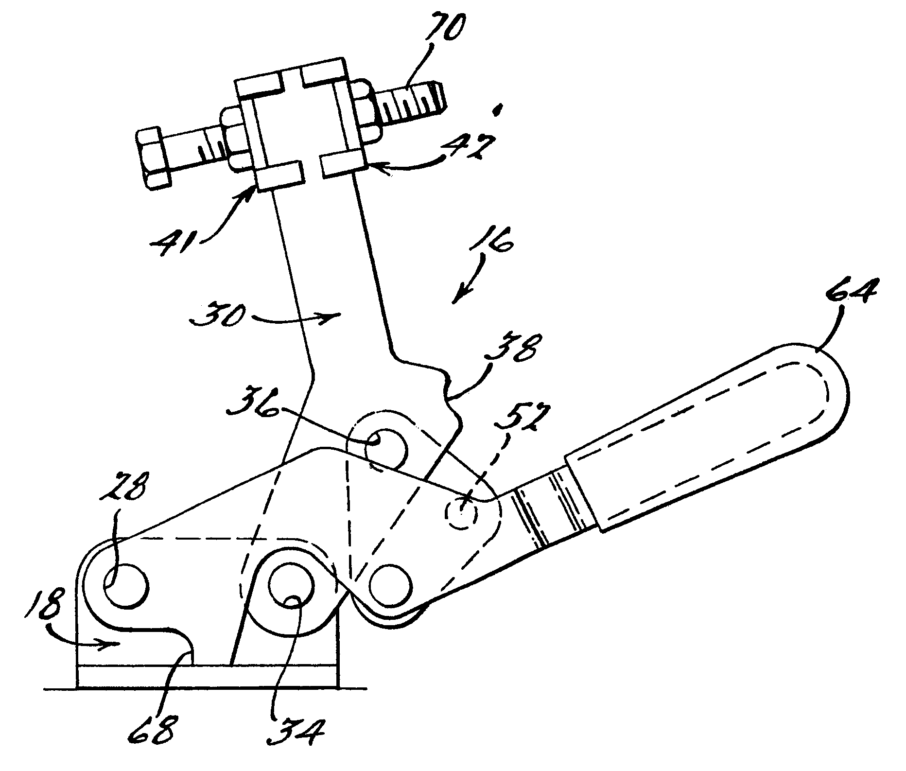
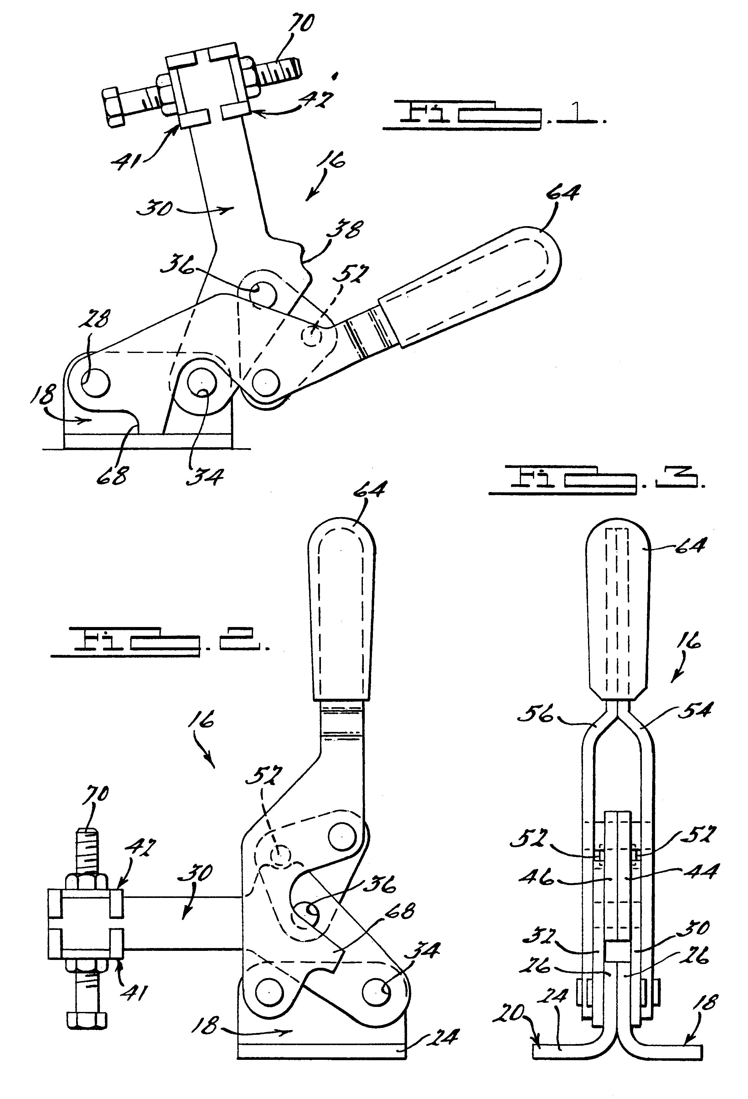
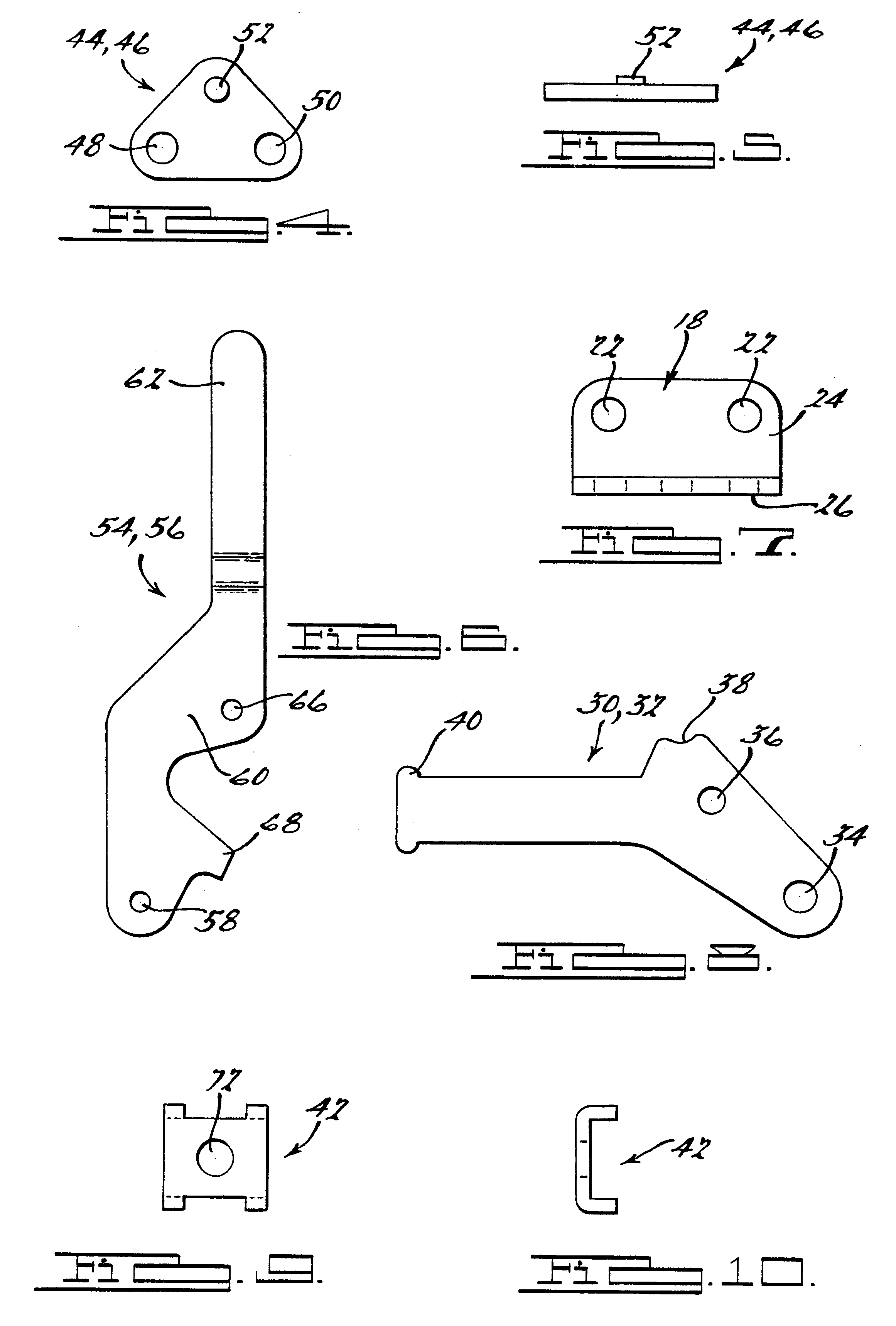
FIGS. 1,2 and 3 show a full embodiment of the hold down clamp 16 according to the present invention. The clamp 16 includes a first and second base member 18, 20 with each base member 18, 20 generally having an L-shaped cross section. The base members 18, 20 include a plurality of orifices 22 through a bottom surface thereof and a side surface thereof. The bottom flange 24 of the base member 18, 20 generally has two orifices 22 therein and those orifices 22 are used to secure, via a fastener, the clamp 16 to a bench, tool or other work device. The upright portion 26 of the base member 18, 20 includes a first and second orifice 28 that are used to connect to other parts of the clamp. The base members 18, 20 are placed such that the upright portion 26 of the base members are in contact with one another and the bottom flanges 24 of the base memb...


PUM


Abstract

A hold down clamp that includes a base member. The hold down clamp further includes a bar pivotally connected to the base member on one end thereof. A handle is pivotally connected to a base member and on an end opposite of the bar. The clamp further includes a link connected to the handle and the bar. The link has a stopper extending from a side thereof. The clamp also includes a holder member connected to an end of the bar.

Description

1. Field of the InventionThe present invention relates to clamps generally, and more particularly relates to a manual hold down clamp.2. Description of Related ArtToggle and hold down clamps have been used and known in the art for many years. A typical hold down or toggle clamp includes a clamping arm which pivots between a released and clamped position. The clamps are used to hold work pieces in place for processing, for clamping two objects to one another, or for clamping an object to a work table or other surface. Toggle and hold down clamps generally are quickly engageable and disengageable to the work piece or object being held. They also provide a considerable holding and clamping force which enables them to hold the work piece or object securely where needed.The prior art toggle clamps can be exemplified in prior U.S. Pat. Nos. 5,921,535, 4,141,543 and 4,011,649. Other prior art clamps are exemplified by De-Sta-Co Industries in Madison Heights, Mich., Model Series 207. Many o...

Claims


Application Information

Patent Timeline
Patent Type & Authority Patents(United States)
IPC IPC(8): B25B5/12B25B5/00
CPCB25B5/12
Inventor DYKSTRA, HENRY
Owner DELAWARE CAPITAL FORMATION INC
Why Eureka
Try Eureka