Cooling device

a cooling device and cooling chamber technology, applied in the direction of cooling/ventilation/heating modification, semiconductor device details, semiconductor/solid-state device details, etc., can solve the problems of mutual cancellation of flow speed, reducing heat transfer performance, and reducing the flow field of the impeding jet, so as to minimise the pressure drop across the impeding cooler and minimise the effect of pressure drop

Inactive Publication Date: 2013-04-09
INT BUSINESS MASCH CORP
View PDF17 Cites 26 Cited by
  • Summary
  • Abstract
  • Description
  • Claims
  • Application Information

AI Technical Summary

Benefits of technology

[0022]Preferably, further hierarchical levels are in contact with the second level, and the structure of the further levels is substantially a replicate of the structure of the second level and enlarged by the predetermined factor. Advantageously, this hierarchical structure for parallel levels, also known as manifolds, may optimally mitigate pressure accumulation and flow distribution issues when feeding coolant fluid to the scaled down impingement arrays.
[0027]The impingement cooler may have surface enhancement features positioned within the impingement gap attached to at least one of the first level and a heated body, wherein the surface enhancement features comprise a plurality of protrusions. Advantageously, the surface enlargement features enhance heat exchange. Where the surface enhancement features extend between the target surface and the jet plate a conductive path is formed which extends to the upper part of the cooler where also the jet plate or manifold structures could contribute to the heat exchange.
[0029]The surface enhancement features may further comprise barrier features regularly positioned along diagonals joining the inlets and outlets of the first level. Advantageously, stagnation points in the impingement gap are substantially eliminated.
[0031]Preferably, the linear parallel protrusions are attached between the first level and the heated body, and modified to form a plurality of microchannels each joining a single inlet and a single outlet. Advantageously, this structure forms a direct conductive path from the heated body to the jet plate, thereby further contributing to the thermal exchange. Also, this embodiment allows relatively short separation of the inlets and outlets which may enable the chip itself to function as a heat spreader.
[0038]a providing step for providing an impingement cooler having a first level adjacent an impingement gap, the first level comprising a layer of inlets and outlets in a distributed array, wherein the inlets and outlets branch from a layer of interdigitated input channels and output channels, and having the impingement cooler in contact with the heat source via the impingement gap, and an impinging step for impinging coolant fluid through the impingement cooler and onto the heat source via the impingement gap, resulting in a minimal pressure drop across the impingement cooler. Advantageously, this method for supplying coolant flow to a target surface on a microprocessor chip minimises pressure drop across the impingement cooler.

Problems solved by technology

However, this introduces the problem of the impinging jet flow field being reduced.
Problematically, due to deflection of peripheral impinging jets, the drainage flow may accumulate at the edge of the impingement gap, which may reduce heat transfer performance.
Further, collision of jet flow from neighboring impinging jets can result in mutual cancellation of flow speed.
Jet impingement arrays as discussed so far are problematic in that they generate a flow field which is inhomogeneous not only locally on the scale of the distance between individual jets but also globally over the area of the larger surface to be cooled, because jets positioned radially outwards from the array center are deflected by the radial flow of coolant coming from the more centrally positioned jets.
Similarly, microchannel coolers generally present poor long-range cooling uniformity because the fluid warms up along the relatively long channels.
Drainage of a jet array in a closed system is done by one exit port—a concept which scales poorly due to the accumulating crossflow.
One of the principal issues of this approach is to provide feed and return flow to the individual cells in a way that is compatible with one sided access to the inlet and outlet arrays and retain the property of low pressure drop.
It is a further problem associated with jet impingement coolers that heat transfer is only possible through the impinged surface.
Surface enlargement done by microscopic features only slightly improves the overall performance of the jet device since they create zones of recirculation and zero flow.
A problem also associated with conventional jet impingement coolers that heat may generally only be removed through the contact between coolant fluid and hot surface and that no heat may be conducted to the upper part of the cooler where also a jet plate or manifold structures could contribute to the heat exchange.
Furthermore, when utilizing parallel manifold structures in conventional jet impingement coolers there is a notable increase in pressure drop in the manifold as nozzle pitch decreases.
Thus, conventional manifold structures do not function adequately at the required reduced physical scales.

Method used


Image

  • Cooling device
  • Cooling device
  • Cooling device

Examples


Embodiment Construction

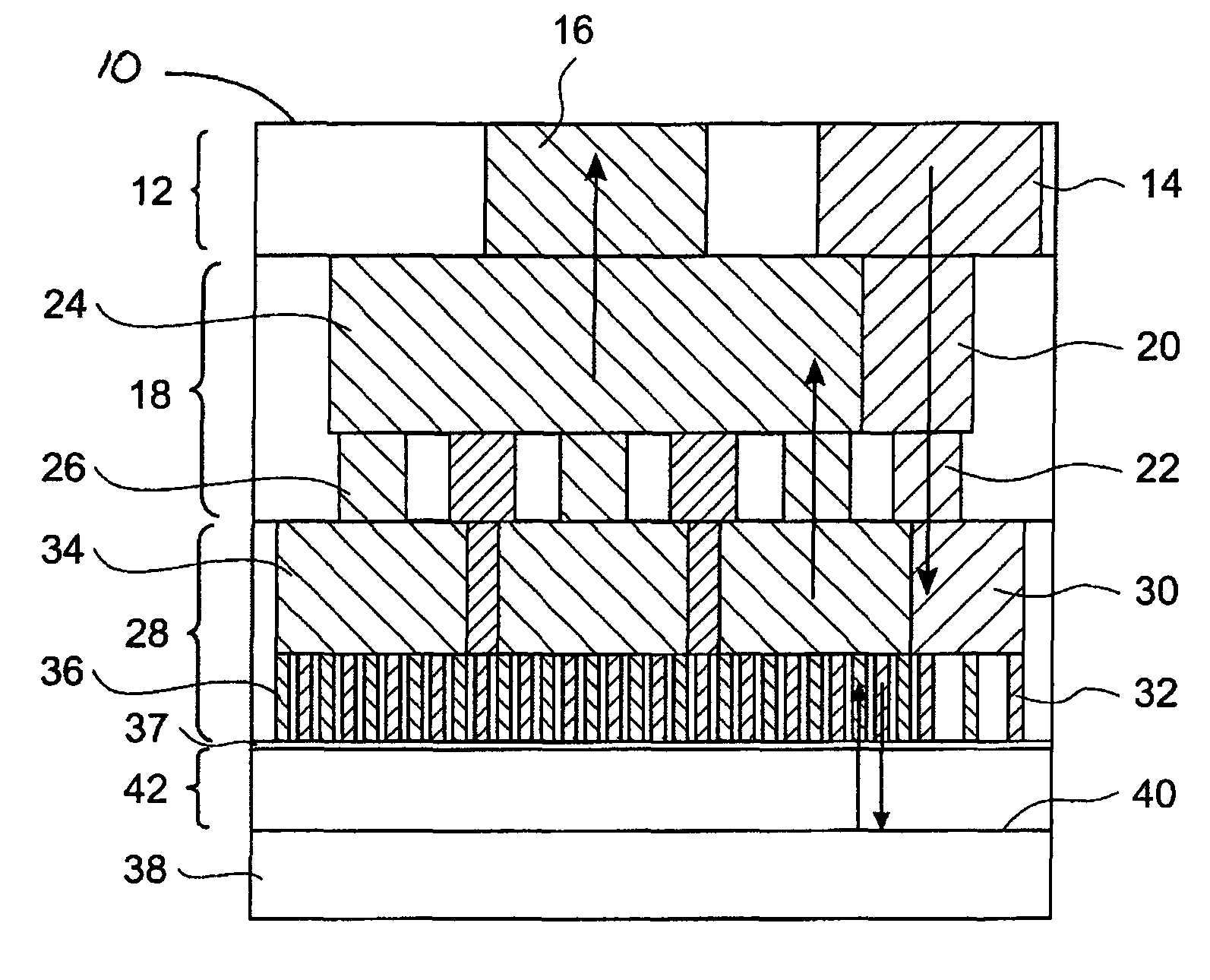
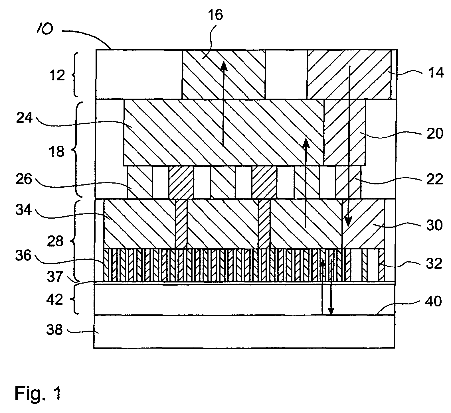
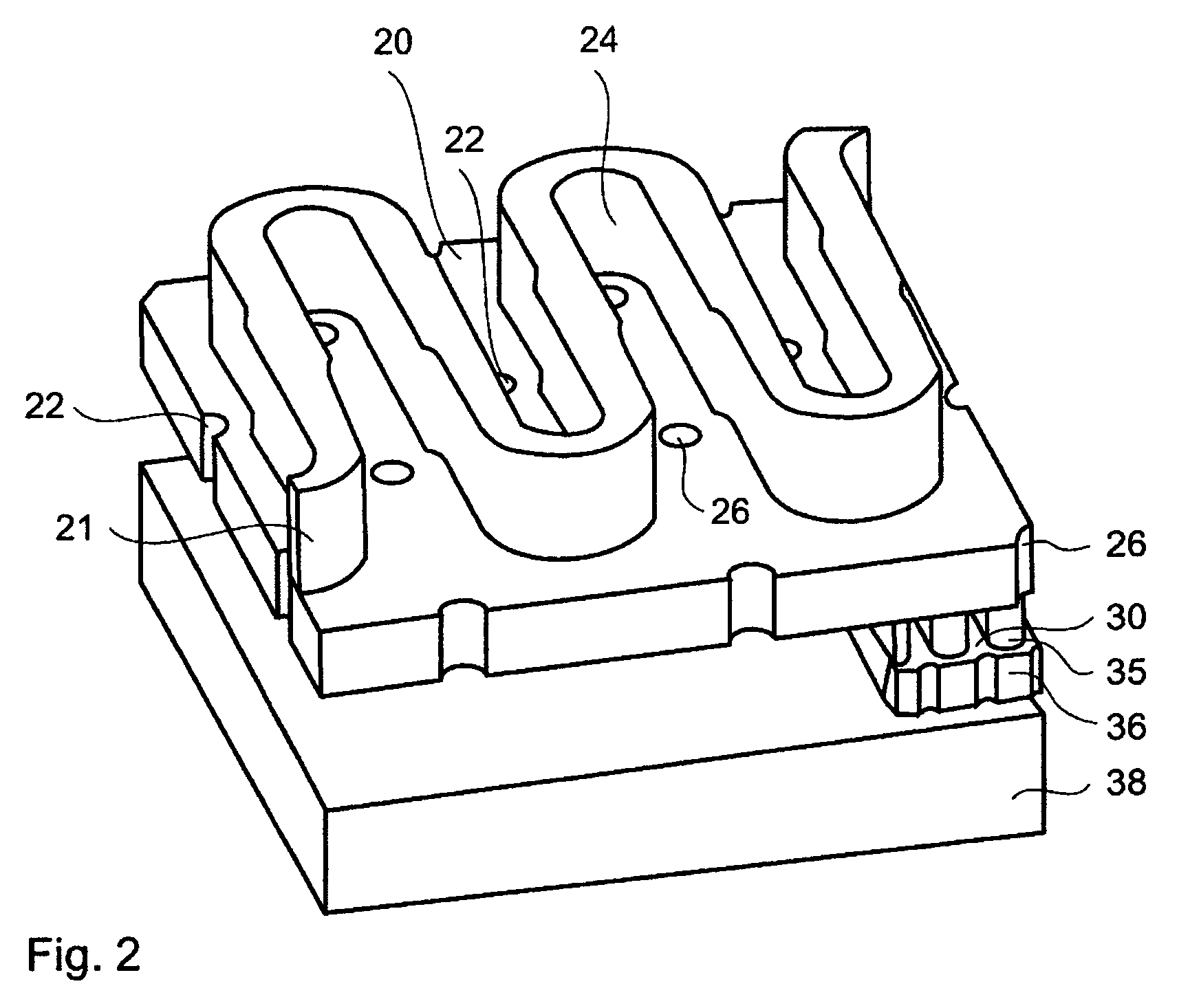
[0063]FIG. 1 shows a cross-sectional view of a portion of an impingement cooler 10 of the present invention. A third level 12 of the impingement cooler 10, also known as an interface layer, comprises a third level inlet 14 and a third level outlet 16. Adjacent to the third level 12 is a second level 18, also known as a manifold layer, comprising a second level manifold input channel 20 connected to several second level inlets 22, and a second level manifold output channel 24 connected to several second level outlets 26. Adjacent to the second level 18 is a first level 28, also known as a jet layer or terminal level, comprising a first level input channel 30 connected to several jet nozzles or first level inlets 32, and a first level output channel 34 connected to several output nozzles or first level outlets 36. The first level inlets 32 and the first level outlets 36 terminate at a jet plate 37. Preferably, the first level inlets 32 and the first level outlets 36 are parallel. A ba...


PUM


Abstract

A cooling device has a large number of closely spaced impinging jets, adjacent an impingement gap, with parallel return paths for supplying coolant flow for the impinging jets with the least possible pressure drop using an interdigitated, branched hierarchical manifold. Surface enhancement features spanning the impingement gap form U-shaped microchannels between single impinging jets and single outlets.

Description

FIELD OF THE INVENTION[0001]This invention relates to a cooling device and particularly relates to impingement coolers in contact with microprocessor chips.TECHNICAL BACKGROUND[0002]In the field of microprocessor chip packages, an effective transfer of thermal energy from a microprocessor chip to a heat sink is important for thermal management of the microprocessor chip.[0003]A known type of active cooling device is an impingement cooler in which coolant flows through channels in the impingement cooler and is then fed through a jet and impinges on the back side of the microprocessor chip. An external pump is used to circulate the coolant between the back side of the microprocessor chip, where heat is absorbed, and a radiator. Heat is subsequently dissipated from the radiator to ambient using, for example, a fan and an air heat exchanger.[0004]A further type of known cooling device for cooling microprocessor chips is a microchannel cooler, as described in “A Practical Implementation ...

Claims


Application Information

Patent Timeline
Patent Type & Authority Patents(United States)
IPC IPC(8): F28F7/02
CPCH01L23/4735H01L2924/0002H01L2924/00
Inventor BRUNSCHWILER, THOMAS J.KLOTER, URSLINDERMAN, RYAN JOESPHMICHEL, BRUNOROTHUIZEN, HUGO E.
Owner INT BUSINESS MASCH CORP
Why Eureka
Try Eureka