Storage system for data encryption

a technology for data encryption and storage system, applied in the field of storage system, can solve the problems of increasing the system's vulnerability against theft of encryption keys, prior art does not give any consideration, etc., and achieves the effect of efficient cooperation

Inactive Publication Date: 2010-02-18
HITACHI LTD
View PDF5 Cites 26 Cited by
  • Summary
  • Abstract
  • Description
  • Claims
  • Application Information

AI Technical Summary

Benefits of technology

[0019]This invention achieves efficient cooperation between more secure and confidential management of e

Problems solved by technology

However, prior art gives no consideration at all to balancing the trade-off between highly secure encryption that users demand, on top of the data replication function which has long been utilized by users, and the host computer performance which is lowered by the encryption and replication functions.
Data encrypted by prior art can be decoded by third parties in the case w

Method used


Image

  • Storage system for data encryption
  • Storage system for data encryption
  • Storage system for data encryption

Examples


first embodiment

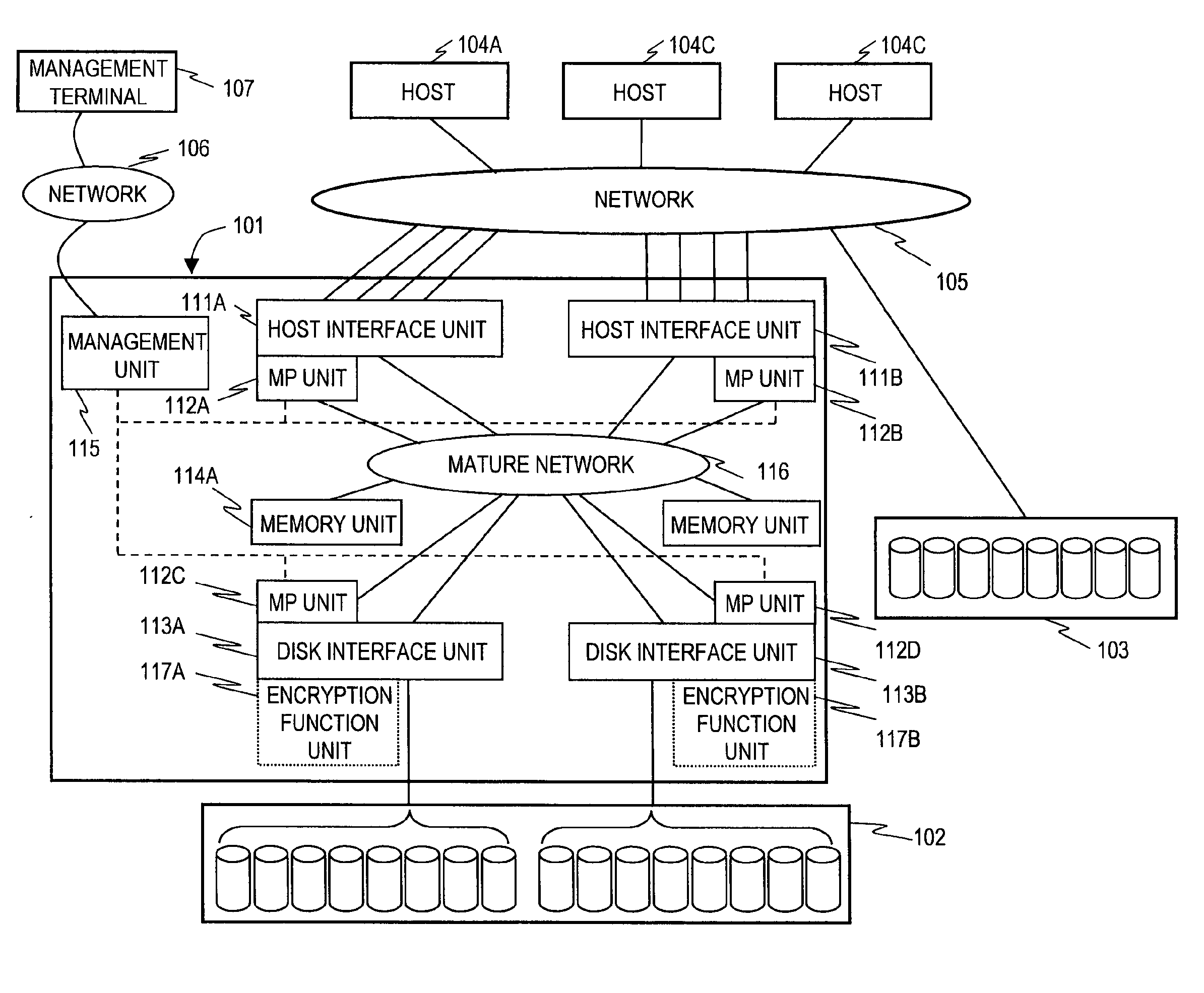
[0043]FIG. 1 is a configuration block diagram of a computer system according to a first embodiment of this invention.

[0044]Plural hosts 104 (104A, 104B, and 104C) are connected to a storage system 101 via a network 105. A disk drive group 102 is connected to the storage system 101. A disk drive group 103 is connected to the network 105. A management terminal 107 is connected to the storage system 101 via a network 106.

[0045]The hosts 104 send a request to the storage system 101 via the network 105, and receive a result of the request via the network 105. The storage system 101 reads data from the disk drive group 102 or 103 following a request from the hosts 104.

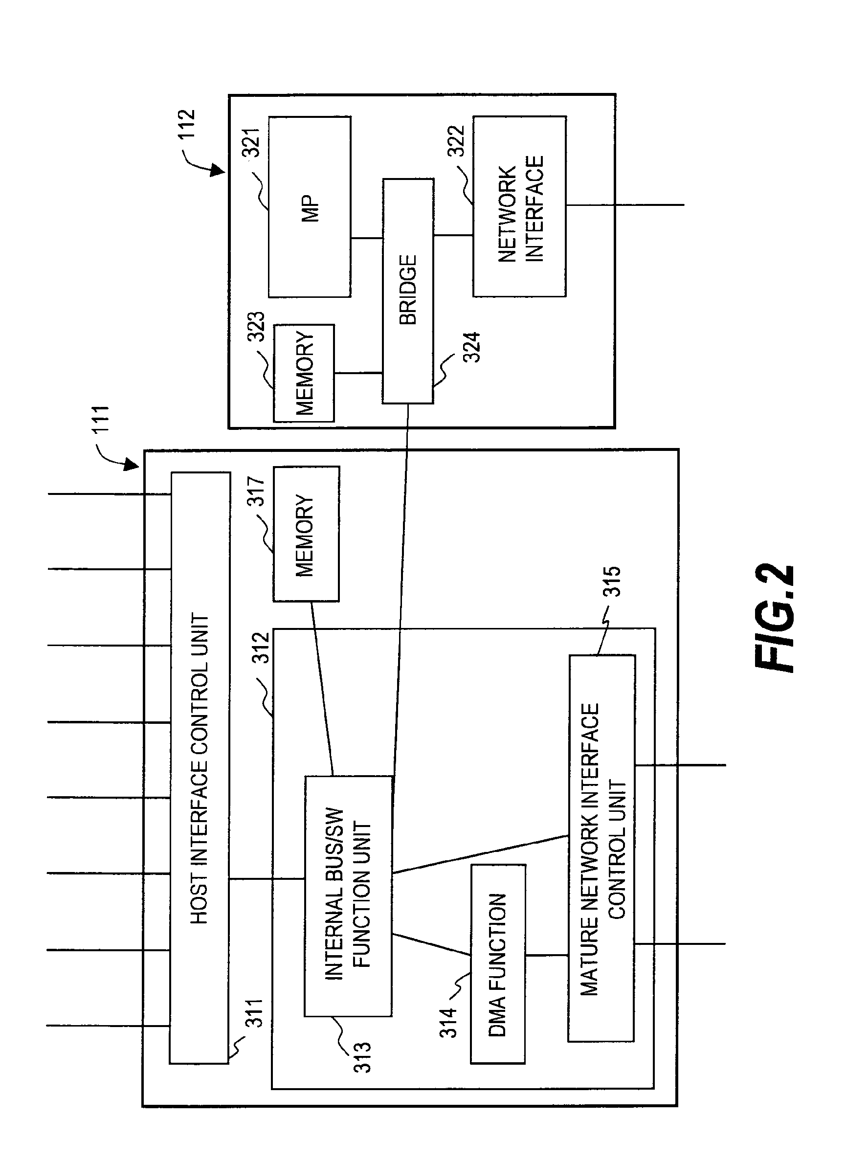
[0046]The storage system 101 has host interface units 111, disk interface units 113, MP (processor) units 112, memory units 114 and a management unit 115, which are interconnected by a mature network 116. The disk interface units 113 have encryption function units 117.

[0047]The host interface units 111 receive a request sent...

second embodiment

[0120]A second embodiment of this invention will be described next.

[0121]In the first embodiment described above, the disk interface units 113 have the encryption function units 117. The encryption units 117 in the second embodiment are attached to other units (the host interface units 111 or the memory units 114) than the disk interface units 113. In the second embodiment, components identical with those in the first embodiment are denoted by the same reference symbols and descriptions thereof are omitted.

[0122]FIG. 9 is an explanatory diagram schematically showing processing in which the hosts 104 write data in the storage system 101 in a computer system according to the second embodiment.

[0123]Logical volumes 00 and 01 are set in the storage system 101. The logical volumes are set in advance upon instruction from the management terminal 107 or the like.

[0124]The actual, physical location of the logical volume 00 is set in the magnetic disk drives 504 of the disk drive group 102. ...

third embodiment

[0151]A third embodiment of this invention will be described next.

[0152]The third embodiment deals with processing of a copy pair made up of logical volumes in a computer system according to the first or second embodiment. In the third embodiment, components identical with those in the first embodiment are denoted by the same reference symbols and descriptions thereof are omitted.

[0153]FIG. 13 is an explanatory diagram schematically showing processing in which the hosts 104 write data in the storage system 101 in a computer system according to the third embodiment.

[0154]In the storage system 101 of this embodiment, the host interface units 111 have the encryption function units 117 as in the second embodiment. The encryption function units 117 may instead be attached to the disk interface units 113 or the memory units 114.

[0155]The storage system 101 of this embodiment has three logical volumes 00, 01 and 02.

[0156]The actual, physical location of the logical volume 00 is set in the ...


PUM


Abstract

A storage system including a host interface connected via a network to a host computer; a disk interface connected to a disk drive; a memory module that stores control information of a cache memory for an access to the disk drive and the storage system; a processor that controls the storage system; a network that interconnects the host interface, the disk interface, the memory module, and the processor; and an encryption module that encrypts data read/written by the host computer, in which the processor reads data from an area of the disk drive from the memory module, decrypts the read data with a corresponding encryption key, encrypts the decrypted data with a different encryption key, and writes the encrypted data in a different area.

Description

CROSS-REFERENCE TO RELATED APPLICATIONS[0001]The present application is a continuation of application Ser. No. 11 / 232,969, filed Sep. 23, 2005; which claims priority from Japanese application P2005-211247 filed on Jul. 21, 2005, the content of which is hereby incorporated by reference into this application.BACKGROUND OF THE INVENTION[0002]This invention relates to a storage system. More specifically, this invention relates to a storage system comprises a storage controller such as a disk array controller, which stores data in one or more disk drives, a tape library controller, an optical disk library controller, a solid-state disk controller (e.g., semiconductor disk controller), or a storage controller that uses a non-volatile memory, typically, flash memory.[0003]Companies and public offices store an increasing amount of digital data recording personal information, and now those who let such information leak have to face legal consequences. It is therefore an urgent task for any o...

Claims


Application Information

Patent Timeline
IPC IPC(8): H04L9/00
CPCG06F11/1076G06F11/1435G06F11/2069H04L63/0428G06F2201/84G06F2221/2107G06F21/6218
Inventor FUJIBAYASHI, AKIRAMIZUNO, MAKIO
Owner HITACHI LTD
Why Eureka
Try Eureka