Buffer tube that results in easy access to and low attenuation of fibers disposed within buffer tube

a buffer tube and fiber technology, applied in the field of buffer tubes, can solve the problems of optical fiber damage and signal attenuation, insufficiently addressed fiber damage or breakage risk, and increased degree of buckling

Inactive Publication Date: 2003-08-05
ALCATEL LUCENT SAS
View PDF14 Cites 223 Cited by
  • Summary
  • Abstract
  • Description
  • Claims
  • Application Information

AI Technical Summary

Problems solved by technology

However, in these patents, access tools are required to both initiate and propagate the tear in the buffer tube using a blade.
Therefore, the risk of fiber damage or breakage and signal attenuation is not adequately addressed.
This deformation of the fiber bundle contributes to the optical fiber damage and signal attenuation.
As additional energy is applied in attempt to pull the ripcord through the buffer tube, the degree of buckling increases.

Method used


Image

  • Buffer tube that results in easy access to and low attenuation of fibers disposed within buffer tube

Examples


Embodiment Construction

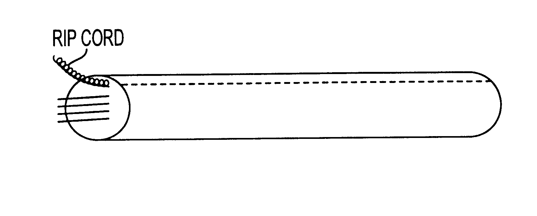
As previously discussed, existing optical fiber access methods use various slitting tools to open the buffer tubes to access several of the fibers in a multiple fiber bundle. Aside from requiring specialized tools, such methods of access potentially attenuate signals on the fibers or may cause damage or breakage. As a first feature of the invention, a ripcord fiber or strands of fibers are laid parallel to the optical fiber bundle. The ripcord may be disposed Hi interior to the buffer tube as shown in FIG. 4(a) or embedded in the tube wall as shown in FIG. 4(b). The ripcord(s) can be color coded or otherwise marked or banded to distinguish it from other components of the fiber bundle, such as the optical fibers. Once an initial access method is used to open the buffer tube, the ripcord fiber(s) can be used to open any desired length of the buffer tube with minimal deformation of the optical fiber bundle. This will occur if the following fracture mechanics criteria is met, that the e...


PUM


Abstract

A buffer tube design that allows easy access to signal carrying fibers disposed within the buffer tube with risk of damaging the signal carrying fibers. The buffer tube can be made with a ripcord disposed within. Additionally, the buffer tube has the mechanical properties that allow the ripcord to be pulled through the tube wall with less energy than is required to bend the signal carrying fibers within. The buffer tube can also be designed without a ripcord in such a way that the mechanical properties allow the tube to be hand torn using a lower amount of energy than required to bend the signal carrying fibers within.

Description

Typically access tools, such as a ring cut and slitter tools, are used to open buffer tubes in order to work on fibers disposed within a buffer tube also containing signal-carrying fibers. Tearing the buffer tube with a fingernail is also a technique used to gain access to the fiber. With these techniques, there is a risk that during access, the tool or fingernail will perturb and cause attenuation to signals carried in live fibers or cause damage to the fiber coating. Such attenuation is on the order of 0.5 dB and higher. An additional concern is that during removal of the buffer tube, the ring cut or breaking away of the buffer tube, a fiber will become damaged or will break.DESCRIPTION OF RELATED ARTIn order to mitigate the risk of damage to optical fibers during the process of buffer tube tearing and removal, several patents have included concepts of including a ripcord filament within the tube, or using specialized tools to slice open a section of the buffer tube. The rip filam...

Claims


Application Information

Patent Timeline
Patent Type & Authority Patents(United States)
IPC IPC(8): G02B6/44
CPCG02B6/4495G02B6/4431
Inventor DALLAS, GEORGE JOHNBARKER, JEFFWITT, GOEFF
Owner ALCATEL LUCENT SAS
Why Eureka
Try Eureka