Ball joint assembly for a piston-and cylinder unit

a technology of ball joint and piston cylinder, which is applied in the direction of shaft and bearing, shaft and rigid shaft coupling, basic electric elements, etc., can solve the problem of spring active in the extraction direction of the ball head

Inactive Publication Date: 2003-08-26
STABILUS
View PDF19 Cites 10 Cited by
  • Summary
  • Abstract
  • Description
  • Claims
  • Application Information

AI Technical Summary

Benefits of technology

In a further advantageous embodiment of the invention, provision is made for the ball cup, starting from its maximum diameter, to make a transition into an undercut-free cylindrical seating for the ball head. Such a ball cup is particularly easy to produce by injection molding technology.

Problems solved by technology

Apart from the large number of parts, a disadvantage here is that the spring is active in the extraction direction of the ball head.

Method used


Image

  • Ball joint assembly for a piston-and cylinder unit
  • Ball joint assembly for a piston-and cylinder unit
  • Ball joint assembly for a piston-and cylinder unit

Examples


Embodiment Construction

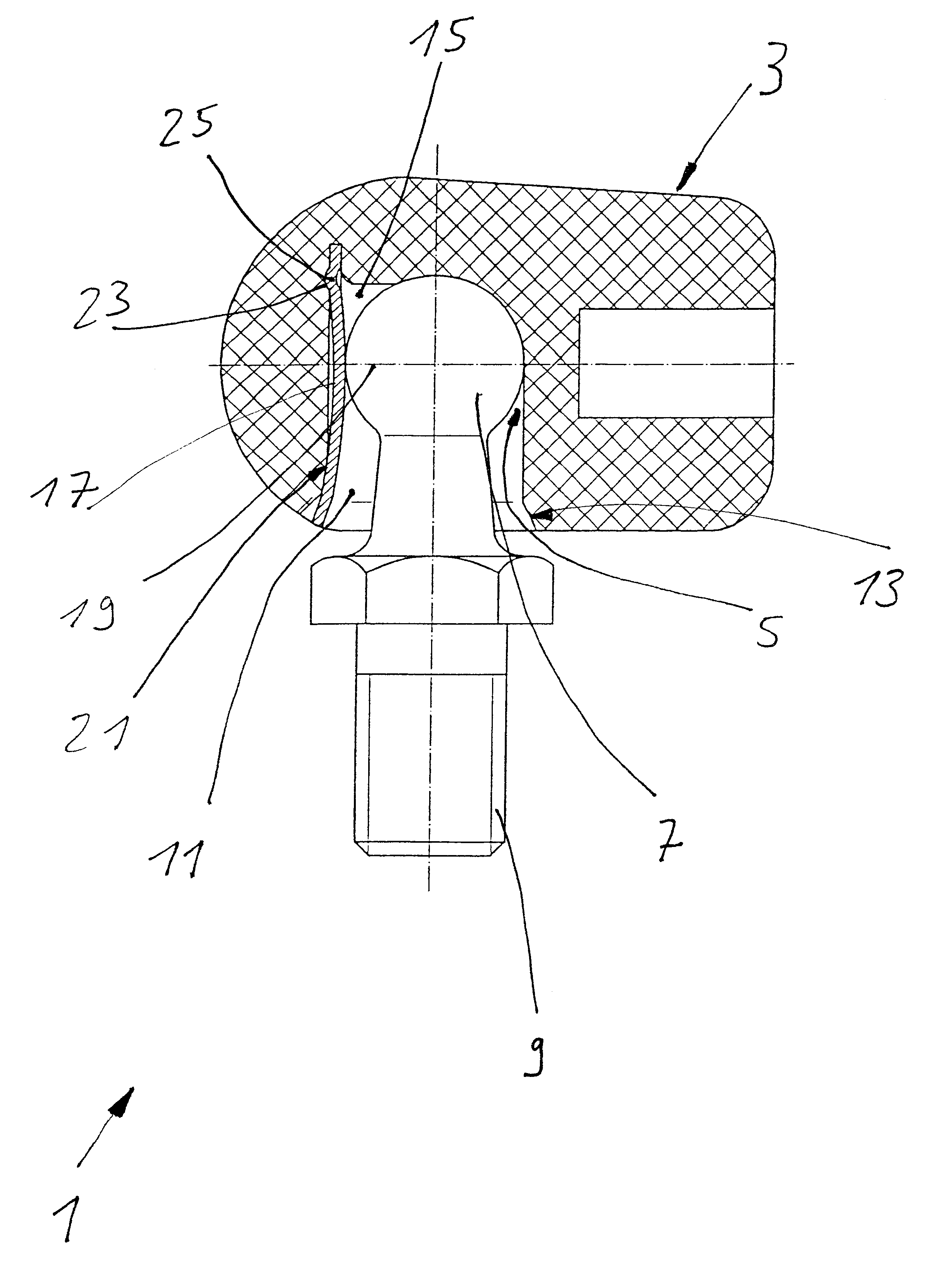
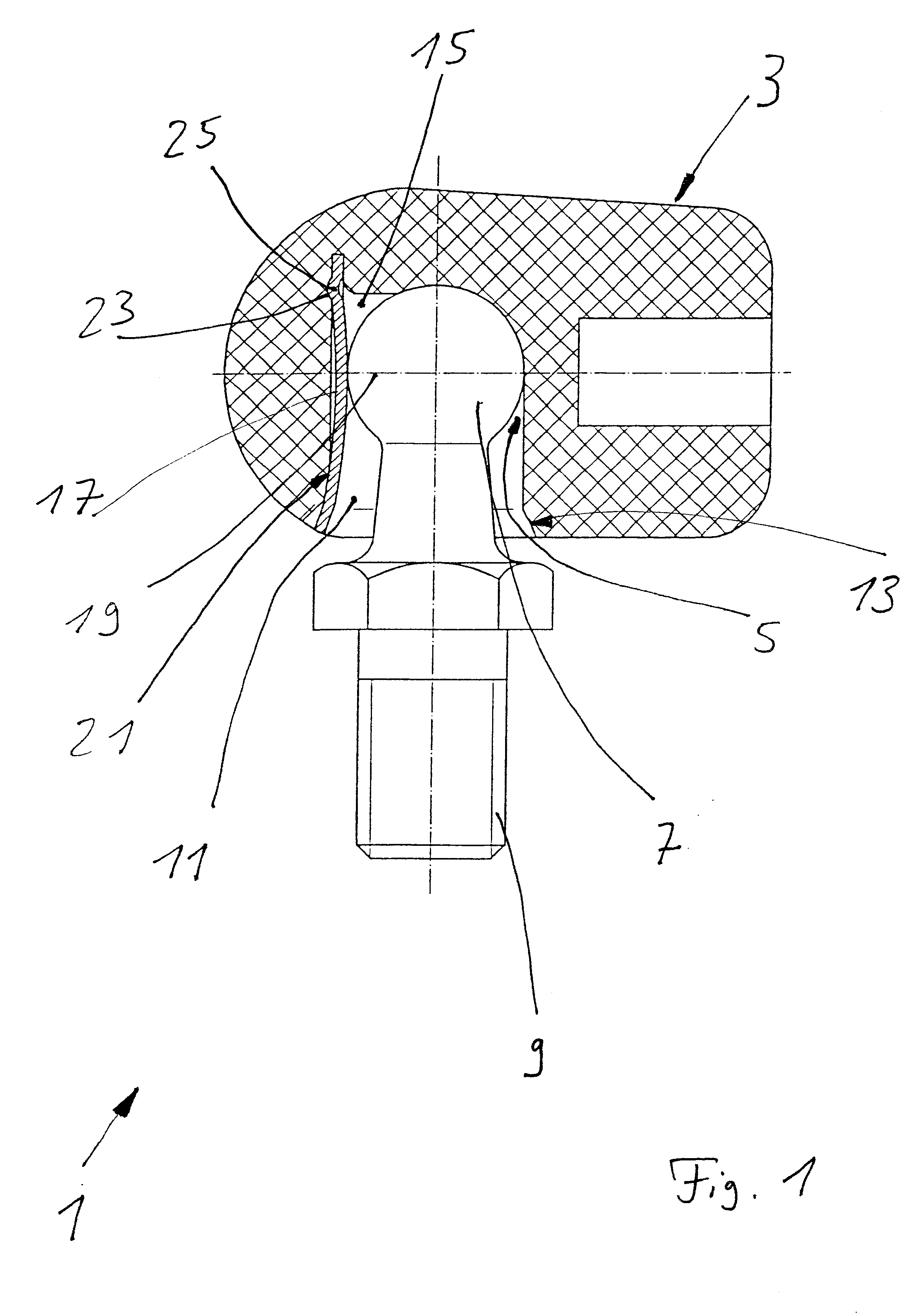
FIG. 1 shows a ball joint assembly 1 as a single part. Ball joint assemblies 1 are used in pneumatic springs in order to permit a three-dimensional pivot movement of the pneumatic spring. Formed within a housing 3 is a ball cup 5, which supports a ball head 7. The ball head 7 is formed with a securing thread 9 in order to enable it to be screwed, for example, into the bodywork of a motor vehicle.

The ball cup 5 has a seat with an outline resembling a hemisphere, which makes a transition into an undercut-free cylindrical entry 11. For easier introduction of the ball head, an installation ramp 13 is formed in the edge region. The ball cup and the entry have a slot 15, into which is inserted a leaf spring 17 bowed in the direction of the ball head. The line of action of the leaf spring engages below an equator 19 of the ball head 7 and is directed toward the ball cup 5. The ends of the leaf spring are supported on an outer surface 21 of the ball cup and of the seating 11.

In order to ens...


PUM


Abstract

A spring element exerts a radial force on a pivotable ball head and thereby prestresses it in a ball cup, the spring element being formed by a leaf spring which extends along the lengthwise axis of the ball head and whose active line of force is directed toward the ball cup below the equator of the ball head.

Description

1. Field of the InventionThe invention relates to a ball joint assembly in accordance with the preamble of patent claim 1.2. Description of the Related ArtDE 42 26 986 discloses a ball joint assembly comprising a pivotable ball head within a ball cup, a spring element exerting a radial force on the ball head and thereby prestressing it in the ball cup. The spring element is formed as a disk spring which is retained in a pocket of the ball cup together with a small plate as a supporting member. Two rows of disk springs with small plates are provided, the spring forces being directed toward the center of the ball head.DE-GM 77 09 622 describes a ball joint assembly whose ball cup is formed in a plurality of parts and is prestressed by a spring acting in the axial direction of the ball pin. Apart from the large number of parts, a disadvantage here is that the spring is active in the extraction direction of the ball head.DE 197 44 796 discloses a joint, especially for a lockable pneumat...

Claims


Application Information

Patent Timeline
Patent Type & Authority Patents(United States)
IPC IPC(8): F16C11/06
CPCF16C11/0647F16C11/069Y10T403/32762Y10T403/32754
Inventor GREB, OLIVERMAURY, HORSTKOCH, KLAUSVOLPEL, STEFANMINTGEN, ROLF
Owner STABILUS
Why Eureka
Try Eureka