
Controlled-polarization marine seismic shear-wave source

a technology of controlled polarization and seismic shear wave, which is applied in seismology, instruments, seismicology for water-covered areas, etc., can solve the problem of not being able to transmit seismic shear wave (either sh-wave or sv-wave) within a body of water

Inactive Publication Date: 2003-09-02
BOLT TECH CORP
View PDF5 Cites 29 Cited by
  • Summary
  • Abstract
  • Description
  • Claims
  • Application Information

AI Technical Summary

Benefits of technology

A swivel is shown provided in a lifting cable line connected to the sling for facilitating turning of azimuthal orientation of the source while it is being supported by the sling and lifting cable.
In addition to the downwardly-projecting blade-teeth elements, the base of the source has a multiplicity of apertures therein for allowing water to flow vertically through the base as it is being lowered through the water suspended by its sling and cable line from a surface ship. These water-flow apertures serve to avoid significant sideways "kiting" or "sailing" through the water as the source is being lowered.

Problems solved by technology

It is not possible to transmit seismic shear waves (either SH-Waves or SV-Waves) within a body of water, because water does not provide nor carry shear elastic force.

Method used


Image

  • Controlled-polarization marine seismic shear-wave source
  • Controlled-polarization marine seismic shear-wave source
  • Controlled-polarization marine seismic shear-wave source

Examples


Embodiment Construction

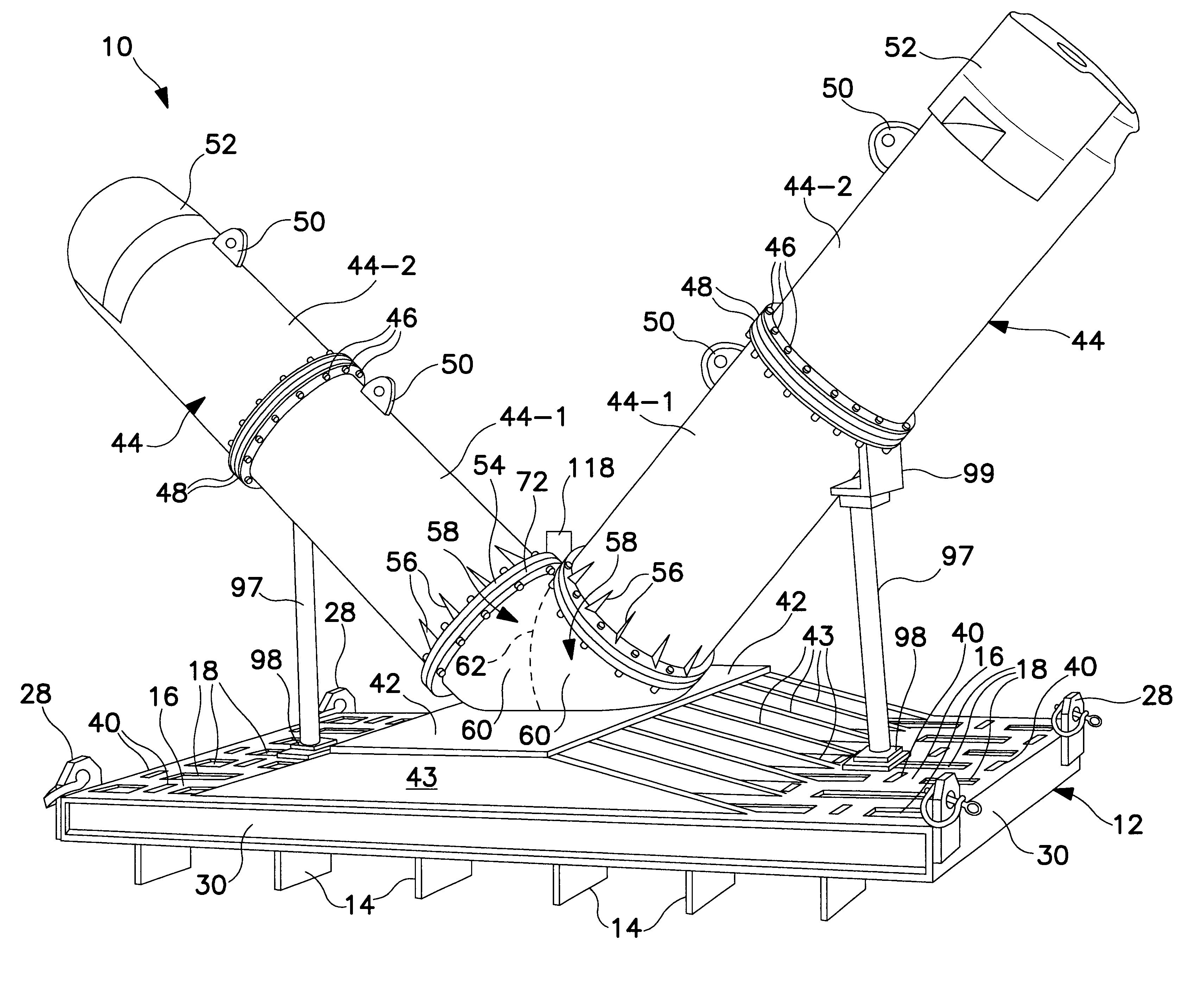
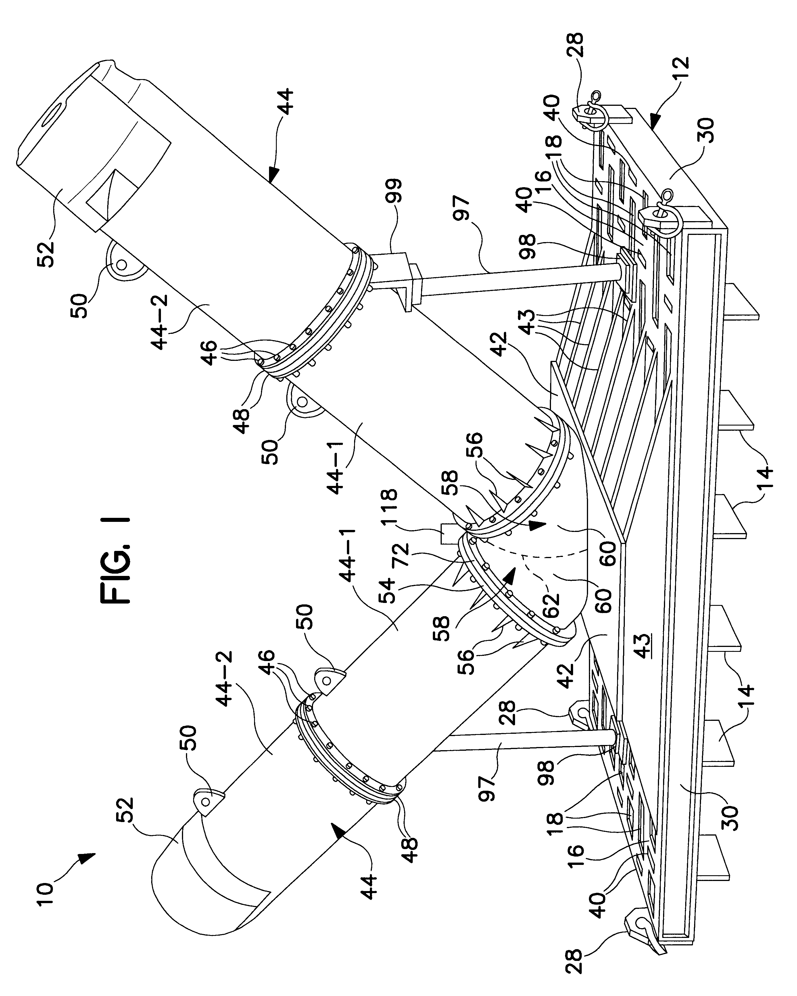
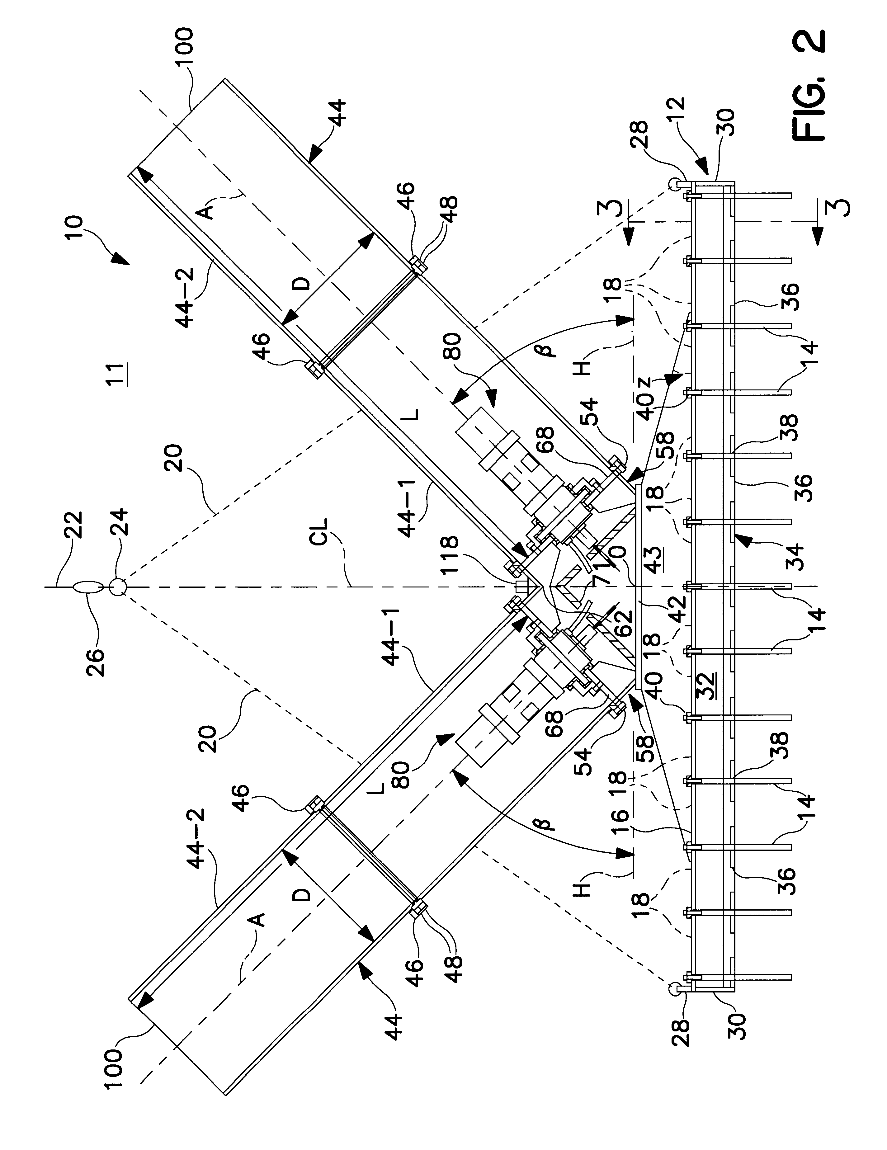
The best mode for carrying out the invention is shown in FIG. 1 with reference to FIGS. 2, 4 and 5. FIG. 3 shows a modified embodiment of this best mode wherein blade teeth are conveniently removable and replaceable. FIG. 1 shows a controlled-polarization marine seismic shear-wave source, generally indicated at 10. This source is adapted to be lowered into a body of water 11 (FIGS. 2, 4 and 5), for example such as a sea, pond, lake, river, estuary, bay, channel, etc. It includes a strong, robust base structure 12 having a multiplicity of downwardly projecting blade-like teeth 14 for augmenting mechanical coupling of horizontal components of force with a seafloor below the body of water 11 where source 10 has been positioned.

The base structure 12 shown in FIGS. 1 and 2 is rectangular seen in plan view in FIG. 5 constructed of suitable structural steel. The base includes a rectangular top plate 16 having a plurality of anti-kiting, i.e., anti-sailing, apertures 18. As shown in FIG. 1,...


PUM


Abstract

Controlled-polarization marine seismic shear-wave source has a base suitable for positioning on a seafloor, beneath a water body. Twin water-blast tubes (seismic-impulse-generation thrusters) are mounted on the base, aimed upwardly, outwardly in opposite directions at equal acute angles beta relative to the base. These blast tubes are positioned symmetrically on opposite sides of vertical centerline CL of the source. When submerged, water enters open mouths at upper ends of the tubes. The base has multiple downwardly projecting blade-like teeth for penetrating into the seafloor. Firing a compressed-air discharger mounted in a lower end of a water-blast tube hurls a powerful slug of water upwardly along the tube, producing a powerful reaction impulse acting downwardly generally parallel with the tube axis. These blade-like teeth, engaging with seafloor material, couple into the seafloor horizontal force components of reaction impulses, thereby propagating simultaneously into the body of the seafloor horizontally-polarized shear waves (SH-Waves) and vertically-polarized shear waves (SV-Waves). Firing one blast tube produces SH-Waves and SV-Waves of first polarities. Firing the other tube produces SH-Waves and SV-Waves of second polarities, respectively opposite to the first polarities. Both tubes are fired simultaneously for propagating compressional P-Waves. While lifting slightly by a swivel cable, azimuthal orientations of the source and resulting shear-wave orientations are controllably changeable by simultaneously firing pneumatic thrusters aimed outwardly from diagonally opposite corners of the base.

Description

This invention is in the field of generating and transmitting into the earth seismic energy waves. More particularly the invention relates to a controlled-polarization marine seismic shear-wave source having a base adapted to be positioned on a seafloor, i.e., on the floor of a body of water, with controllable azimuthal orientation for predetermining the polarization-orientation of shear waves being generated and propagated into the body of the seafloor material.Seismic shear waves are transverse elastic waves in which particle motion is perpendicular to the direction of propagation. Horizontally polarized seismic shear waves (SH-Waves) are particularly useful in subsurface exploration and may be generated by subjecting a localized area of a-surface of the earth (seafloor in this instance) to impulses which have a horizontal component of force perpendicular to the direction of propagation of the SH-Waves.Also, vertically polarized seismic shear waves (SV-Waves) have utility in subsu...

Claims


Application Information

Patent Timeline
IPC IPC(8): G01V1/02G01V1/053G01V1/38
CPCG01V1/053G01V1/3808
Inventor CHELMINSKI, PAULHUMPHREYS, RODNEY A. E.
Owner BOLT TECH CORP
Learn More