
Tool case

a tool box and tool technology, applied in the field of tool boxes, can solve the problems of insufficient inability to store a large amount of tools, hammers, pneumatic tools, etc., and achieve the effect of reducing the storage space of the conventional tool box

Inactive Publication Date: 2003-09-02
CHANG YEH CHING
View PDF5 Cites 10 Cited by
  • Summary
  • Abstract
  • Description
  • Claims
  • Application Information

AI Technical Summary

Benefits of technology

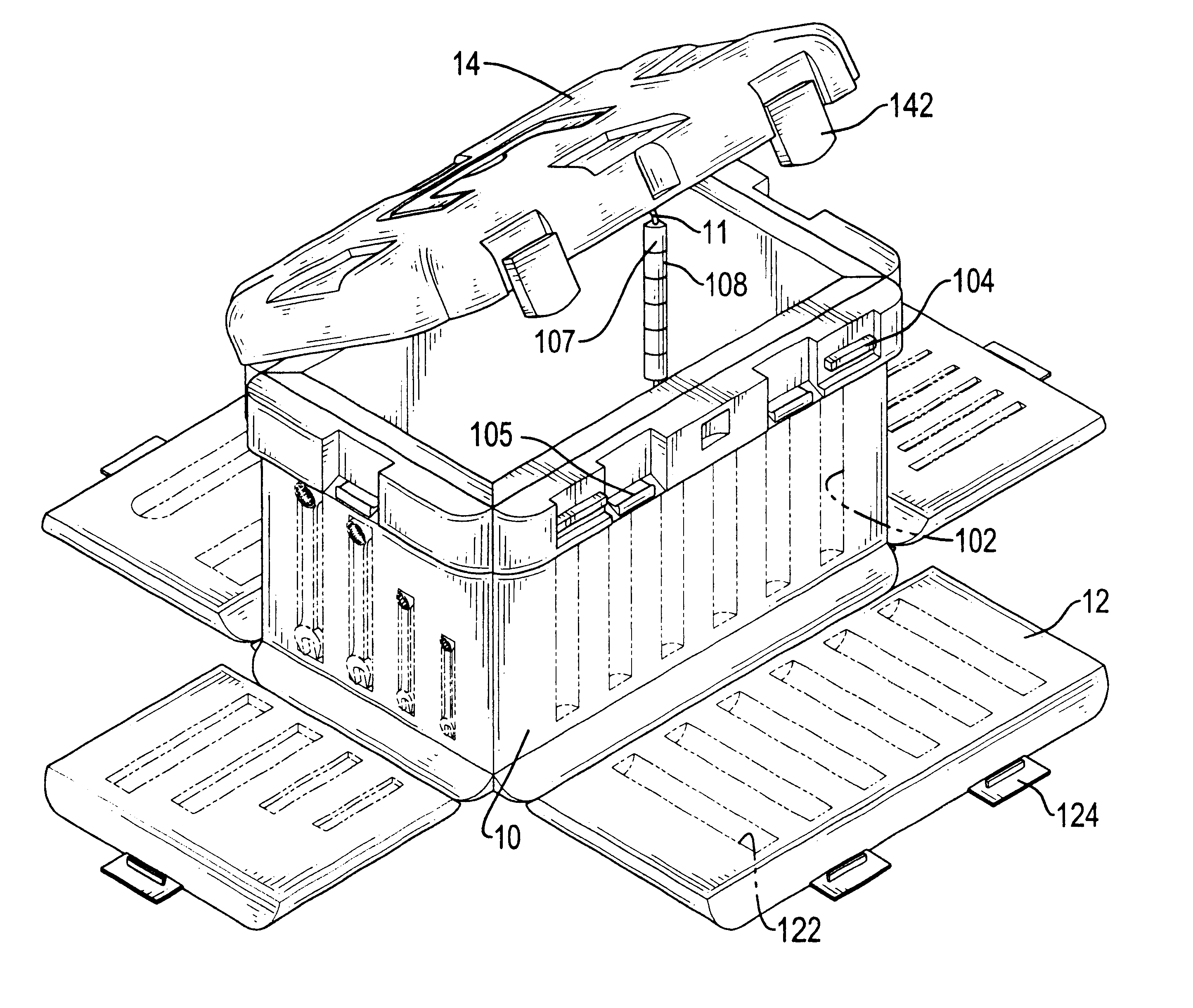
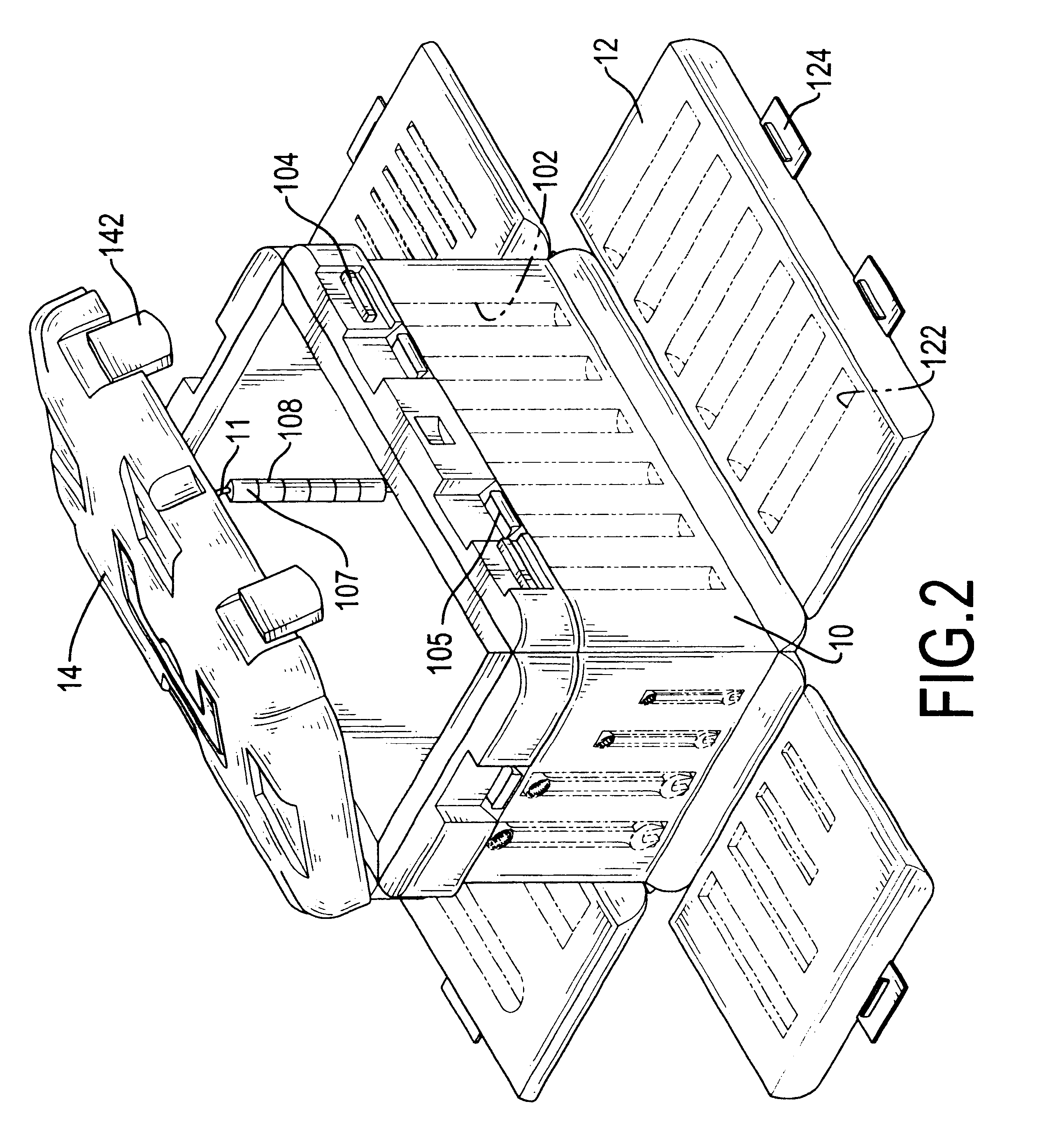
The bottom plate (16) is attached to the side plates to close the bottom opening of the containing space and to hold the tools stored in the containing space. The upper cover (14) is pivotally attached to one of the side plates (10) to close the containing space. An engaging device is mounted between the upper cover(14) and one of the side plates (10) away from the side plate (10) on which the upper cover (14) is mounted. The engaging device comprises at least one knob (105) formed on the side plate (10) corresponding to the upper cover (14) and a first engaging tab (142) extending from the upper cover (14) and corresponding to each respective knob (105). When the upper cover (14) is closed, the first engaging tabs (142) will respectively engage with the corresponding knobs (105) on the side plate (10). With the engagement of the first engaging tabs (142) and knobs (105), the top opening of the containing space is closed with the upper cover (14). This can keep the tools stored in the containing space from escaping from the containing space when the tool case is transported. In addition, a handle (not numbered) is mounted on the upper cover (14), and it is convenient for a user to carry the tool case with the handle.
In such an arrangement, the tools can be selectively stored in the recesses (102,122) in the side plates (10) and the side covers (14). With multiple side plates (10) and side covers (12), the storing spacing of the tool case is large. Additionally, some large tools, such as hammers, pneumatic tools and so on, can be stored in the containing space between the side plates (10). The tool case in accordance with the present invention can be used for storing and for carrying different types of tools, such that the use of the tool case is versatile.

Problems solved by technology

However, the space for storing tools in the conventional tool case is only defined in corresponding sides of the body and the cover, and the storing space of the conventional tool case is not enough to carry a large amount of tools.
In addition, some large tools, such as hammers, pneumatic tools, saws and so on, cannot be stored in the conventional tool case, such that the usage of the conventional tool case is not versatile.

Method used


Image

  • Tool case
  • Tool case
  • Tool case

Examples


Embodiment Construction

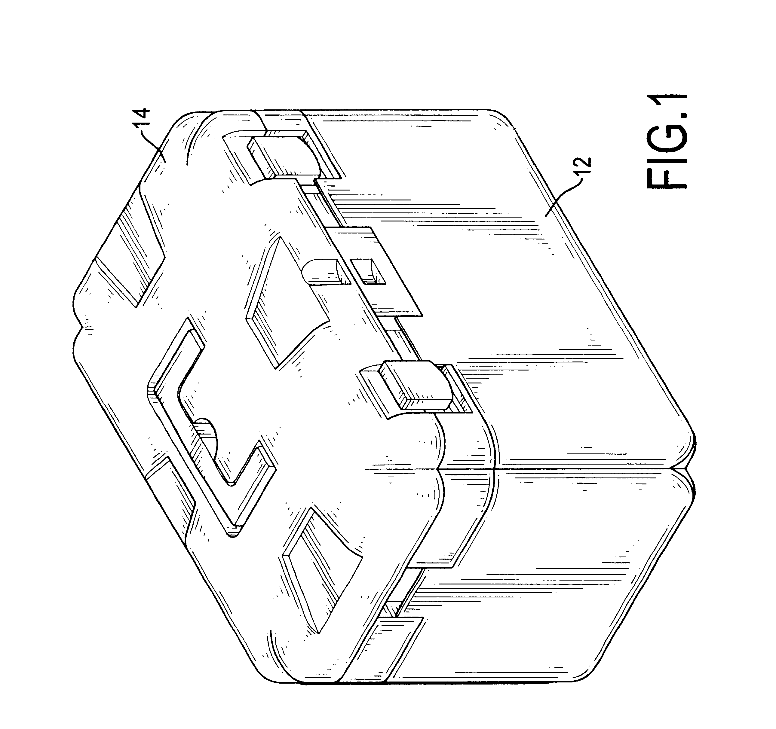
With reference to FIGS. 1 to 3, a tool case in accordance with the present invention comprises multiple side plates (10), a bottom plate (16), an upper cover (14) and multiple side covers (12). Each side plate (10) has an outer side, an inner side and two ends. Two ends of each side plate (10) are respectively connected with adjacent side plates (10) to define a containing space with a top opening and a bottom opening between the inner sides of the side plates (10). Multiple recesses (102) are defined in the outer side of each respective side plate (10) for receiving tools, such as wrenches, bits, drills and so on.

The bottom plate (16) is attached to the side plates to close the bottom opening of the containing space and to hold the tools stored in the containing space. The upper cover (14) is pivotally attached to one of the side plates (10) to close the containing space. An engaging device is mounted between the upper cover(14) and one of the side plates (10) away from the side pl...


PUM


Abstract

A tool case has multiple side plates, a bottom plate, an upper cover and multiple side covers. The side plates are connected with each other to define a containing space for storing large tools. Multiple recesses are defined in the outer side of each respective side plate for receiving tools. Each side cover is pivotally connected to one of the side plates and has an inner side with multiple recesses to receive tools. Accordingly, the space for storing tools in the tool case is large and many, and the use of the tool case is versatile.

Description

1. Field of the InventionThe present invention relates to a tool case, and more particularly to a tool case which has a large and many storing space for storing different shapes and types of tools.2. Description of Related ArtTo convenient carry tools to a desired location, a tool case is used. A conventional tool case in accordance with the prior art comprises a body and a cover pivotally attached to the body. Multiple recesses are respectively defined in the body and the cover to receive tools.However, the space for storing tools in the conventional tool case is only defined in corresponding sides of the body and the cover, and the storing space of the conventional tool case is not enough to carry a large amount of tools. In addition, some large tools, such as hammers, pneumatic tools, saws and so on, cannot be stored in the conventional tool case, such that the usage of the conventional tool case is not versatile.To overcome the shortcomings, the present invention tends to provid...

Claims


Application Information

Patent Timeline
Patent Type & Authority Patents(United States)
IPC IPC(8): B25H3/00B25H3/02
CPCB25H3/023Y10S312/902B25H3/02
Inventor CHANG, YEH-CHING
Owner CHANG YEH CHING
Learn More