Image compression apparatus and decoding apparatus suited to lossless image compression

a lossless image and compression apparatus technology, applied in the field of image compression encoding and decoding, can solve the problems of strong demand for lossless or near-lossless image compression, significant reduction of compression rate, and reversible (lossless) and quasi-reversible (near-lossless) compression

Inactive Publication Date: 2003-09-02
PANASONIC CORP
View PDF2 Cites 56 Cited by
  • Summary
  • Abstract
  • Description
  • Claims
  • Application Information

AI Technical Summary

Problems solved by technology

As a result, there is a very strong demand in lossless or near-lossless image compression.
When compressing an image using segmentation, there is the problem that improving the detail in the reproduction image inevitably results in division into segments of large areas in the original image where there are only minute differences in luminance values, or in other words, large areas may be regarded having a uniform luminance value.
This significantly reduces the compression rate, and is major drawback for reversible (lossless) and quasi-reversible (near-lossless) compression.
Compressed image data obtained through an image compression technique using segmentation where each segment has its own luminance value is unsuited to progressive reproduction.
When such data is decoded, even if it were possible to produce the reproduction image in accordance with gradual changes in luminance values, it would still be difficult to perform progressive reproduction in accordance with the changes in resolution and in the shapes of segments.

Method used


Image

  • Image compression apparatus and decoding apparatus suited to lossless image compression
  • Image compression apparatus and decoding apparatus suited to lossless image compression
  • Image compression apparatus and decoding apparatus suited to lossless image compression

Examples


first embodiment

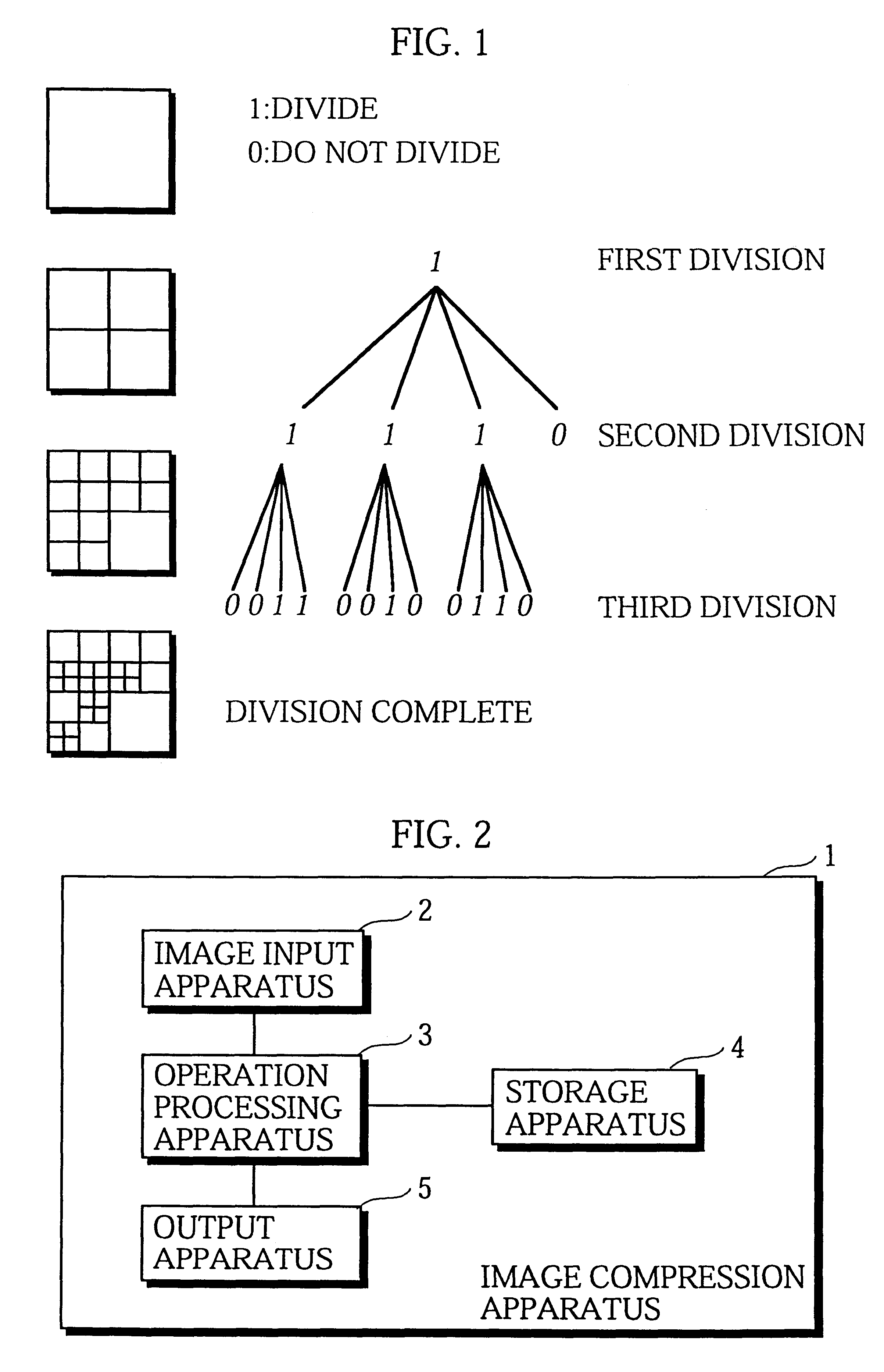
FIG. 2 shows a simplified construction of the image compression apparatus in the first embodiment of the present invention.

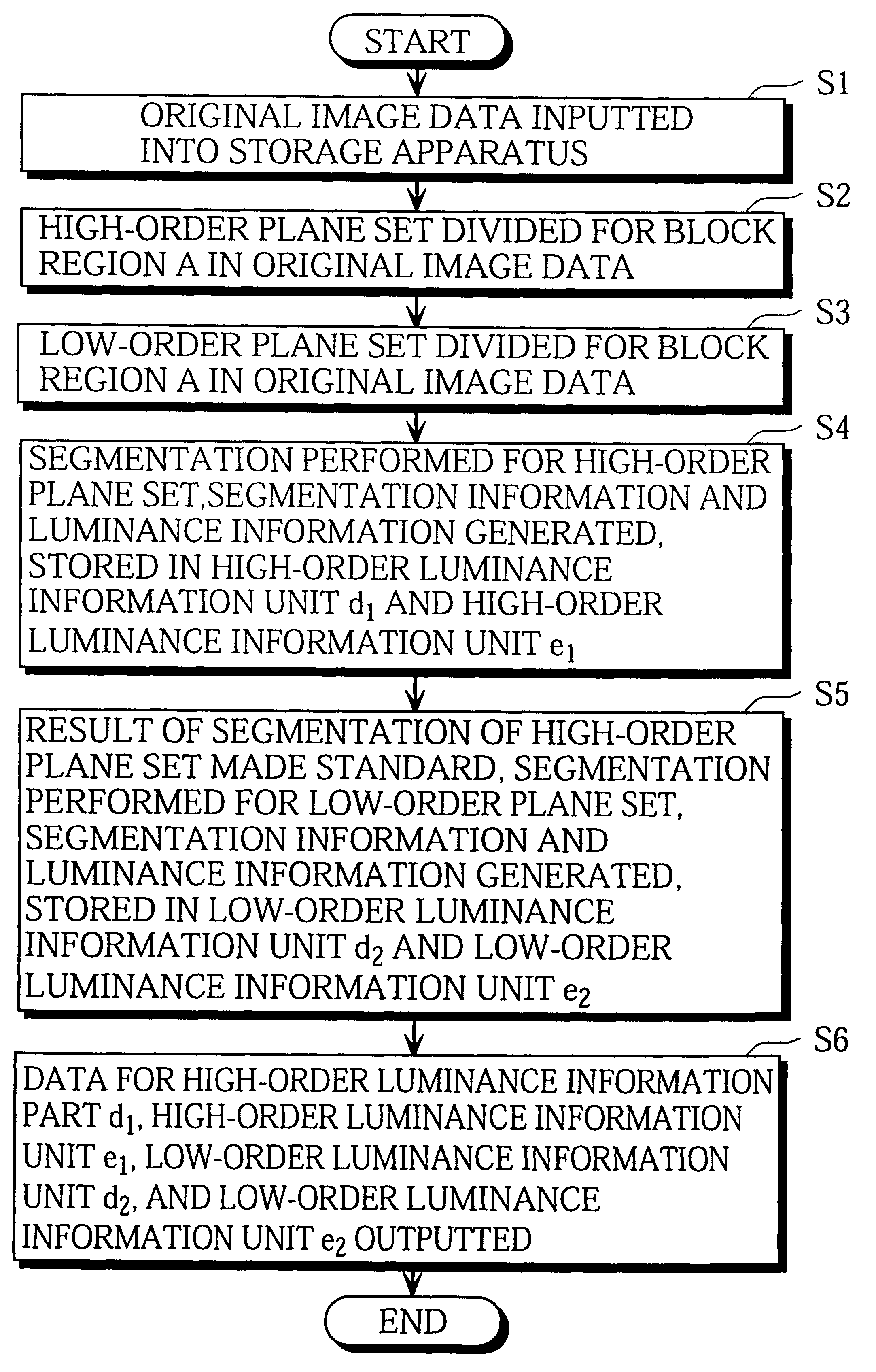
The image compression apparatus 1 generates compressed image data by compressing original image data using quadtree segmentation for bit plane sets. This image compression apparatus 1 includes: an image input apparatus 2 for inputting the original image data; an operation processing apparatus 3 for performing operations such as segmentation on the inputted original image data; a storage apparatus 4 for storing the inputted original image data and data, such as segmentation information, generated by the image compression apparatus 1; and an output apparatus 5 for outputting the compressed image data generated by the operation processing apparatus 3 as a bitstream.

The settings described below are assumed for the present embodiment.

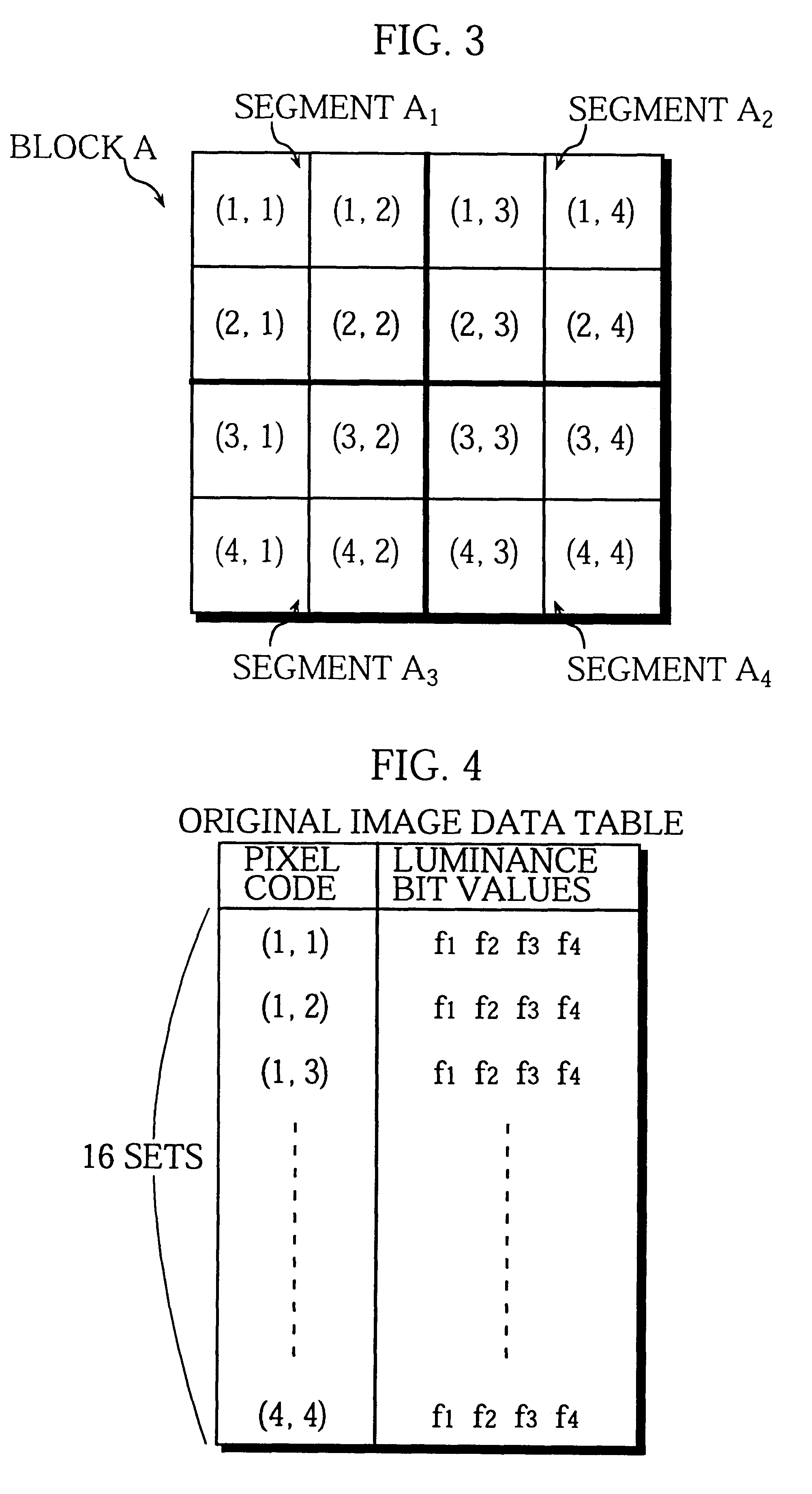
The inputted original image data is digital image data where each pixel that composes a frame is assigned a luminance value. In this ex...

second embodiment

This second embodiment relates to an image decoding apparatus that corresponds to the image compression device of the first embodiment.

FIG. 11 shows the simplified configuration of the image decoding apparatus to which the present embodiment relates.

This image decoding apparatus 11 generates decoded data by decoding the compressed image data generated by the image compression apparatus 1 of the first embodiment. The image decoding apparatus 11 is composed of an input apparatus 12 for inputting the compressed image data, an operation processing apparatus 13 for reading the segmentation information and luminance information for the high-order plane set and low-order plane set from the compressed image data and performing region calculation and the like to decode the compressed image data, a storage apparatus 14 for storing the inputted data and segmentation information, and an image output apparatus 15 for outputting a decoded and reproduced image.

The settings for the high-order plane...

third embodiment

The overall construction of the image compression apparatus in this embodiment is the same as in the first embodiment, so that the same reference numerals as FIG. 2 are used.

The composition of the original image data, the settings for the block region A, and the division judgement condition are also the same as in the first embodiment. However, the present embodiment differs from the first embodiment in that the first embodiment only divides the original image data into a high-order plane set and a low-order plane set and generates compressed image data for each. The present embodiment operates so that when dividing the original image data into a 1.sup.st plane set that corresponds to the high-order plane set and a 2.sup.nd plane set that corresponds to the low-order plane set, if the 2.sup.nd plane set does not include the LSB plane, segmentation is again performed for the 2.sup.nd plane set to produce a 3.sup.rd or later plane set below the 2.sup.nd plane set.

As before, a variety ...


PUM


Abstract

An image compression apparatus for outputting compressed image information that is suited to progressive image reproduction where completely lossless reproduction is possible without having to use large amounts of compressed image information. A decoding apparatus decodes the compressed image information and performs reproduction. The image compression apparatus performs image compression with a first segmentation for a first plane set that includes at one bit plane in block image information in the original image information. As a result, first region information composed of segmentation information showing a first segmentation result and luminance information is produced. The image compression apparatus also performs image compression with a second segmentation for a second plane set that includes at least one bit plane adjacent to the first plane set. Here, the first segmentation result is used as a standard. As a result, second region information composed of segmentation information and luminance information is produced. Compressed image information is then generated and outputted based on the first and second region information.

Description

(1) Field of the InventionThe present invention relates to image compression encoding and decoding.(2) Related ArtAdvances in network technology and multimedia applications in recent years have created a greater need to handle large amounts of data, such as image files.Image files generally include a large amount of data, and effectively need to be compressed before transmission. To address this need, image compression methods which use region division (hereinafter "segmentation") have been developed.Image compression methods that use segmentation use a predetermined judgement standard (called a "division judgement condition") to divide image regions into segments.As an example method of processing an image region, Image Coding by Adaptive Tree-Structured Segmentation, IEEE, Trans. Info., Vol.38, No.6, pp.1755-1767 (1992) teaches a method for dividing a region into convex polygons, while Image Compression via Improved Quad-tree Decomposition Algorithms, IEEE Image. Proc., Vol.3, No....

Claims


Application Information

Patent Timeline
Patent Type & Authority Patents(United States)
IPC IPC(8): G06T9/00G06T9/40H04N7/26H04N7/30H04N1/41H04N19/00H04N19/119H04N19/194H04N19/20H04N19/34H04N19/96
CPCG06T9/40H04N19/70H04N19/30H04N19/60H04N19/37H04N19/17H04N19/34
Inventor YAMAUCHI, MASAKI
Owner PANASONIC CORP
Why Eureka
Try Eureka