Apparatus and method for bond force control

a technology of apparatus and bond head, applied in the direction of soldering apparatus, manufacturing tools,auxillary welding devices, etc., can solve the problems of more vibration of the bond head, unable to meet the requirements of ideal bond force control, and requiring a longer settling tim

Inactive Publication Date: 2003-09-09
ASM ASSEMBLY AUTOMATION LTD
View PDF30 Cites 48 Cited by
  • Summary
  • Abstract
  • Description
  • Claims
  • Application Information

AI Technical Summary

Benefits of technology

The present invention still further provides a method of preventing vibrations of a collet assembly in a die bond head during movement of the said bond head either in the z direction prior to engaging the substrate or translational movement, comprising generating a force to move said collet assembly against a stop means while said bond head is being moved.

Problems solved by technology

To date prior art techniques have failed to satisfactorily meet all the requirements for ideal bond force control.
This means that if a very small bond force is required, the preload of the spring must also be very small, but this in turn has the disadvantage of resulting in more vibrations of the bond head following movement which will thus require a longer settling time in the bonding operation.
Another problem that arises from simply reducing the preload of the spring to enable a small bonding force to be applied, is that the contact of the spring with the moving assembly 2 and the bond head housing 3 may be poor and the bond force may be non-linear.
The price for this, however, is that the range of the output force produced by the spring is reduced and this method can only really work with small bond force applications.
A difficulty with this design, however, is that the response time is slow.
A related disadvantage is that there is a relatively large impact force.
If this impact force is too large it can damage the die, but the slow response time of a pneumatic system makes it very difficult to control the impact force.
It is also difficult to control the bond force with any great accuracy.
The main disadvantage, however, is that the output bond force is relatively small, and to create a large bond force when such is required, a large and correspondingly heavy solenoid must be used.
Generally, solenoid systems are only suitable for use in applications where a small bond force is required.

Method used


Image

  • Apparatus and method for bond force control
  • Apparatus and method for bond force control
  • Apparatus and method for bond force control

Examples


Embodiment Construction

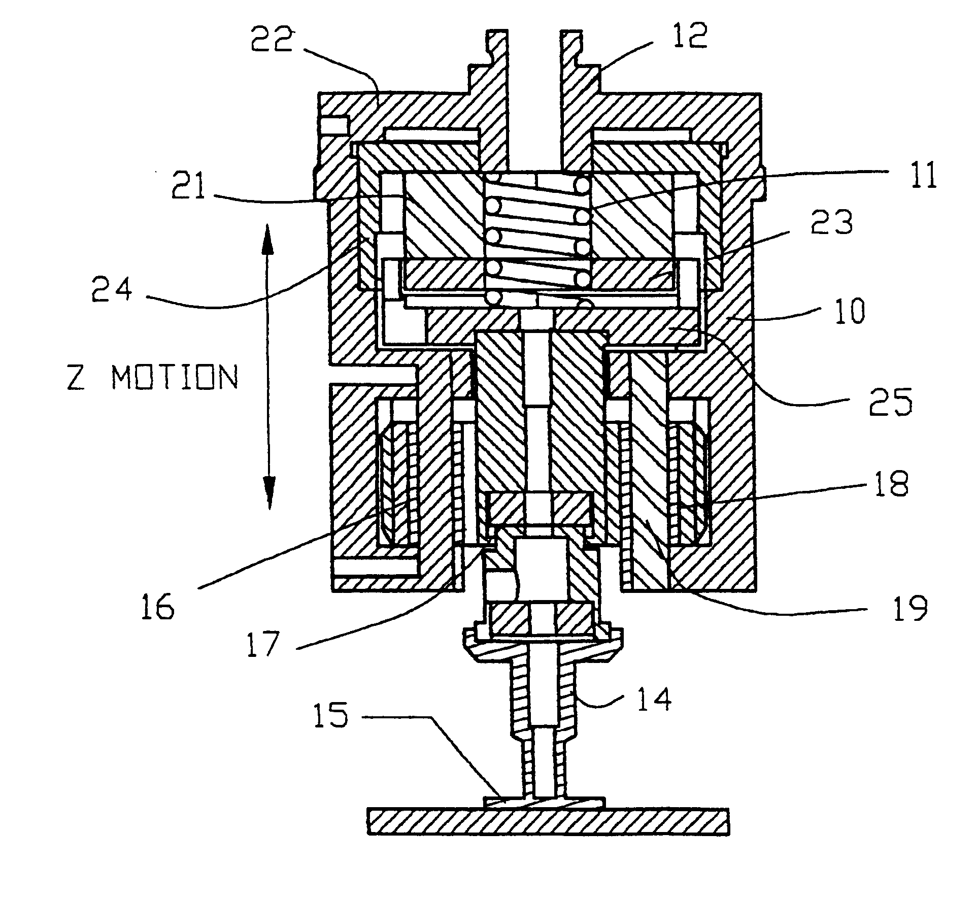
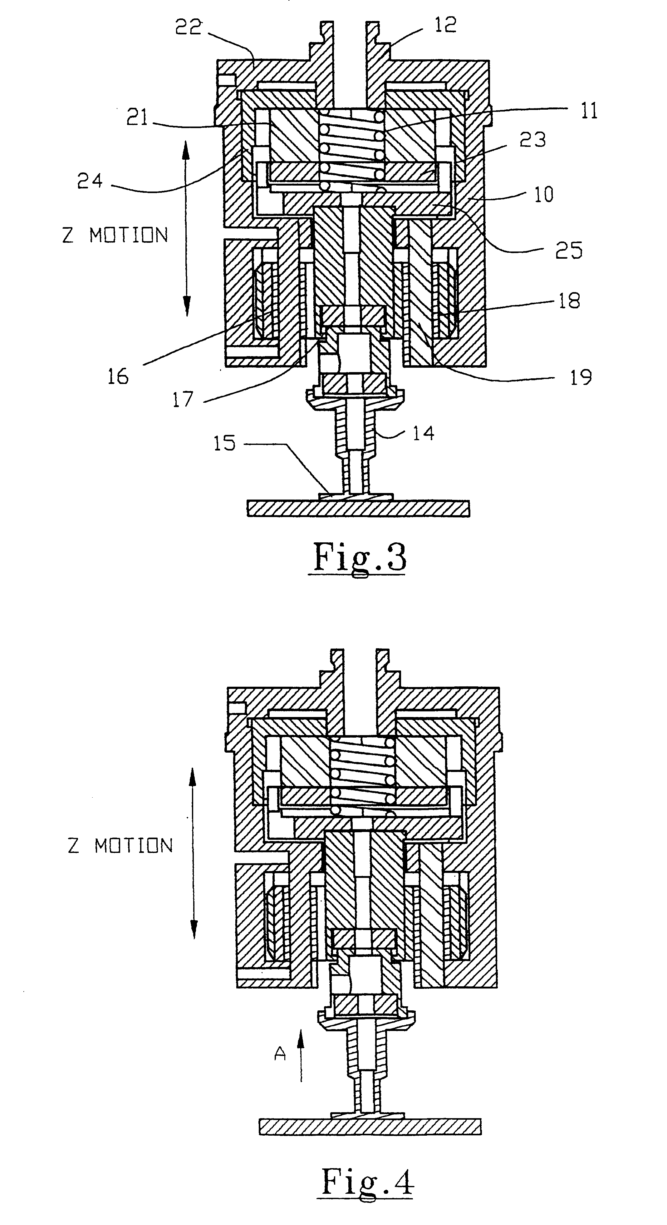
An embodiment of the present invention will now be described with reference to FIGS. 3 and 4. As will be seen in more detail from the following description, an important aspect of the present invention is that the apparatus and method involves the provision of a first primary bond force generating means such as a compression spring, and a second compensatory bond force generating means that is capable of rapidly and accurately generating a compensating bond force that may be positive or negative to provide fine control of the primary bond force. This compensatory bond force may be generated, for example, by a motor.

Referring to FIGS. 3 and 4, a bond head according to an embodiment of the invention comprises a bracket 10 for supporting the bond force generating means. The primary bond force generating means comprises a compression spring 11 fixed between one end of a shaft 12 and a mount 25 for a bond force motor coil to be described below. Compression spring 11 is provided with a pr...


PUM

PropertyMeasurementUnit
bond forceaaaaaaaaaa
forceaaaaaaaaaa
impact forceaaaaaaaaaa

Abstract

An apparatus and method are disclosed for providing bond force in a die bonding operation. The apparatus comprises means such as a compression spring for generating a primary bond force, and additionally means such as a voice coil for generating a compensatory bond force. The compensatory bond force can be controlled by varying the current to the voice coil so as to add to or reduce the bond force whereby a bond force comprising the sum of the primary bond force and the compensatory bond force may be controlled.

Description

This invention relates to an apparatus and method for bond force control, and in particular to such control in a die bonding operation.In a die bonding operation in a semiconductor assembly and manufacturing process, a bond head may pick a die (which may be an electronic device such as a semiconducting integrated circuit device) at a first location and will move the die to a second location at which the die is to be bonded to a substrate, such as a circuit board. The bond head will then move downwardly (this is known as the z-direction) until the die touches the substrate. In order to apply a required bond force during the bond operation, the bond head may be driven downwardly further to exert a required force on the die.Apparatus and methods for controlling this bond force need to meet a number of conflicting requirements. For example, they should preferably be able to apply a bond force over a wide range, should be susceptible to feedback and control, and should be able to respond...

Claims


Application Information

Patent Timeline
Patent Type & Authority Patents(United States)
IPC IPC(8): B23K20/02H01L21/00
CPCB23K20/02H01L21/67092B23K2201/40B23K2101/40
Inventor WONG, SUN KUENWAN, MING YEUNG LUKE
Owner ASM ASSEMBLY AUTOMATION LTD
Why Eureka
Try Eureka