Dynamic depth-of-field emulation based on eye-tracking

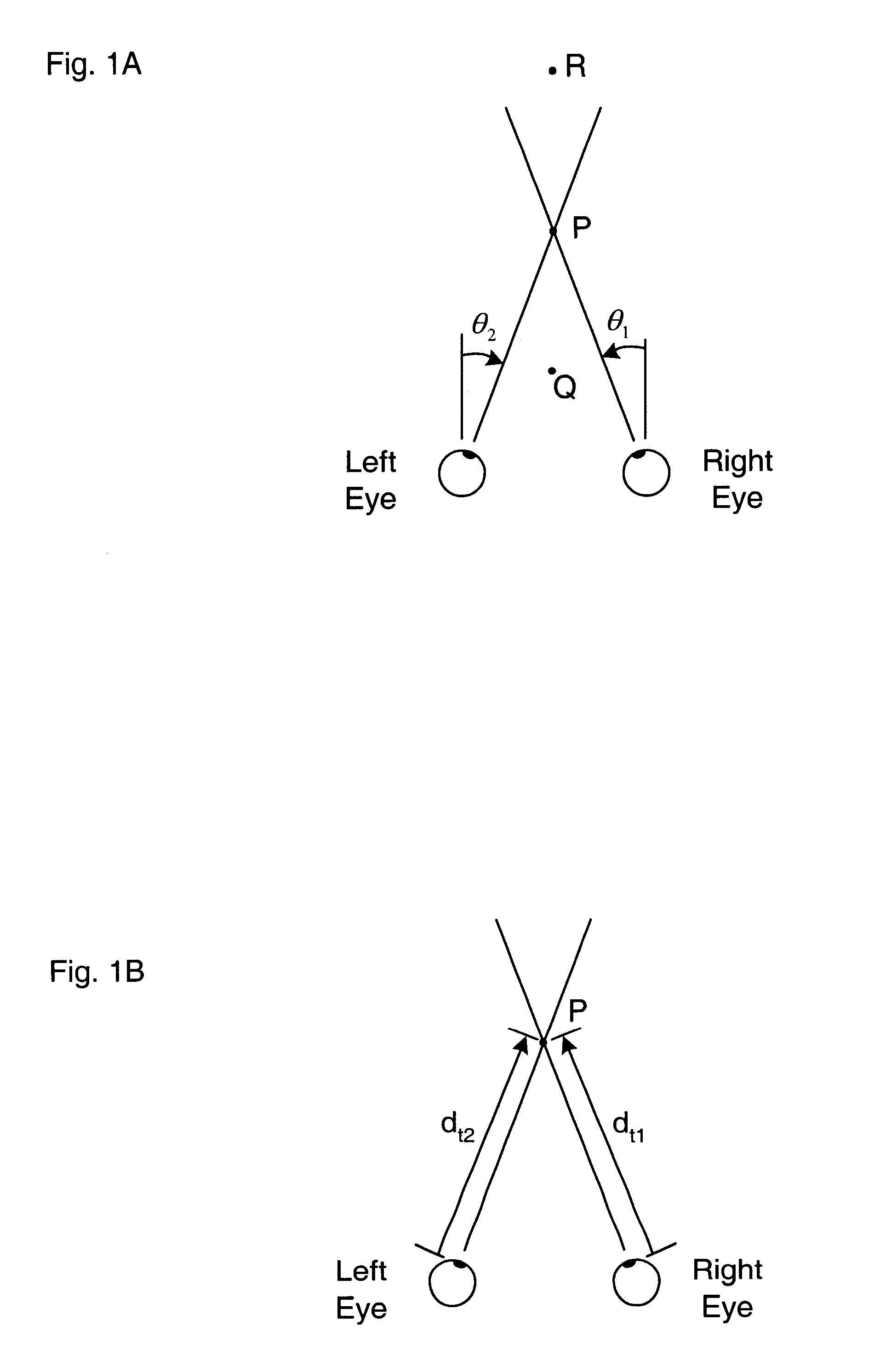
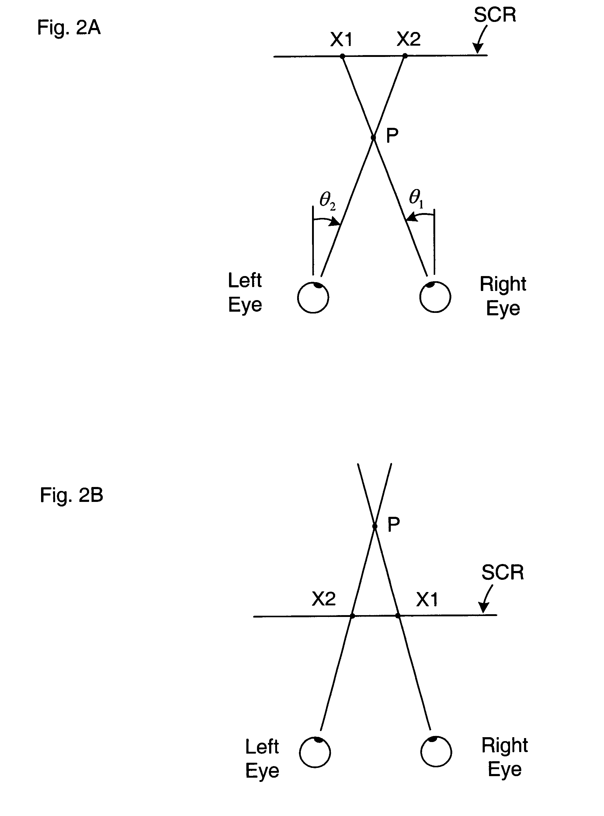
a depth-of-field emulation and eye tracking technology, applied in the field of 3d graphics, can solve the problems of viewers finding it difficult (or impossible) to override the brain's tendency to focus at the intersection point, and it is difficult even intentionally to achieve focus

Inactive Publication Date: 2003-09-09
ORACLE INT CORP
View PDF5 Cites 24 Cited by
  • Summary
  • Abstract
  • Description
  • Claims
  • Application Information

AI Technical Summary

Problems solved by technology

For most people, it is somewhat difficult even intentionally to achieve focus distances d.sub.f1 and d.sub.f2 that are significantly larger than or small than the distances to the intersection point.
Many viewers find it difficult (or impossible) to override the brain's tendency to focus at the intersection point.
When the viewer is observing artificially generated objects in response to stereo video, the tendency to focus at the intersection point is disadvantageous.
This increasing blur may actually discourage the brain control system from converging the eyes towards the virtual object to the extent where image fusion can occur.

Method used


Image

  • Dynamic depth-of-field emulation based on eye-tracking
  • Dynamic depth-of-field emulation based on eye-tracking
  • Dynamic depth-of-field emulation based on eye-tracking

Examples


Embodiment Construction

FIG. 3--Graphics System 100

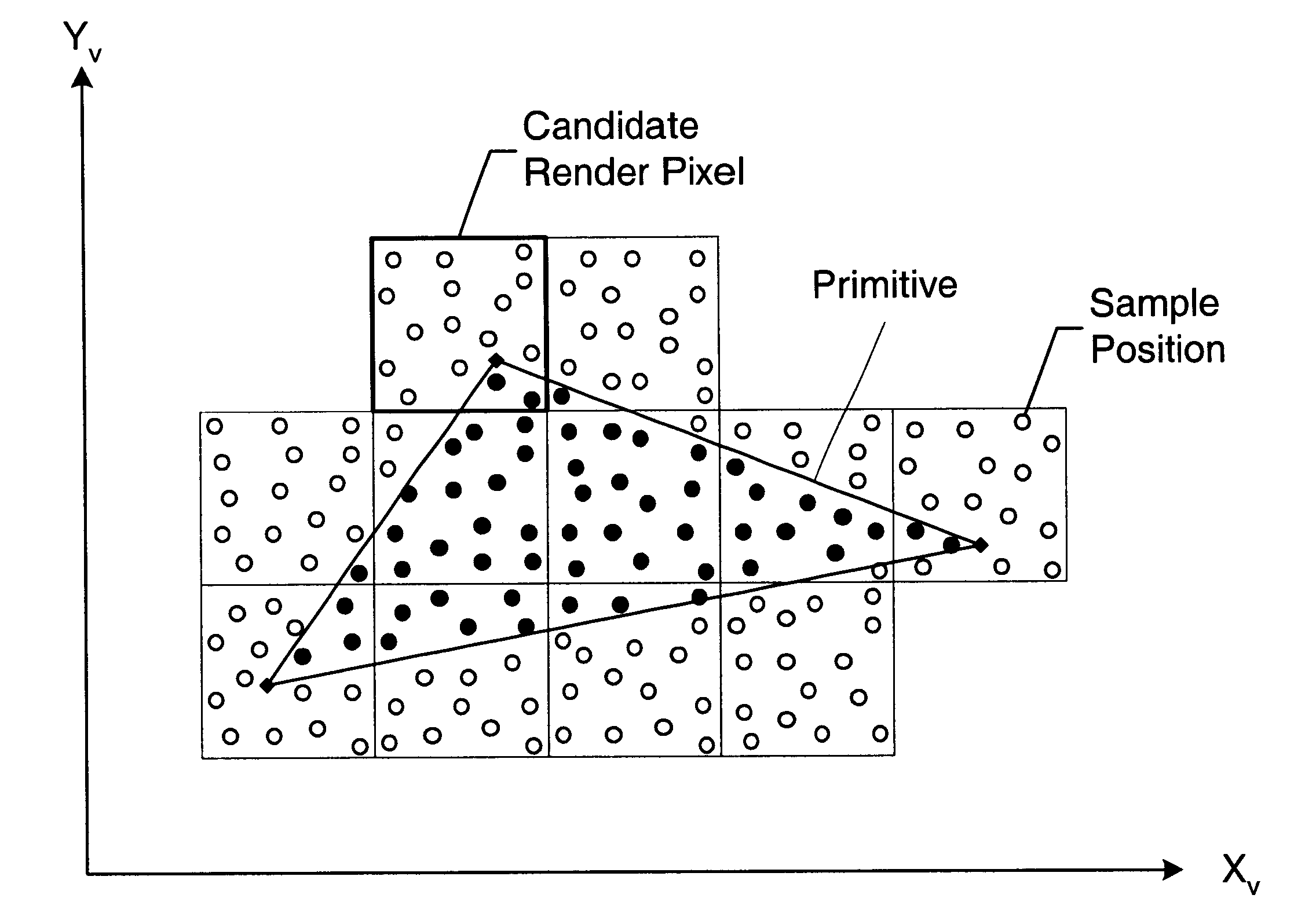
FIG. 3 illustrates one embodiment of a graphics system 100 configured to generate video signals in response to an input stream of 3D graphics data. Graphics system 100 may receive the 3D graphics data from a graphics API (i.e. an application programmer's interface such as OpenGL.RTM., Java 3D.TM., PHIGS or Renderman.RTM. running on a host computer system. For example, the graphics API may store the 3D graphics data in a system memory, and graphics system 100 may read the graphics data from the system memory. The graphics API may be controlled by a graphics application (e.g. a video game, flight simulator, a CAD application or a virtual reality application) also running on the host computer system.

The 3D graphics data may comprise a stream of graphics primitives. Examples of graphics primitives include polygons, parametric surfaces, splines, non-uniform rational B-splines (NURBS), sub-division surfaces, fractals, volume primitives, and particle systems. The...


PUM


Abstract

A graphics system comprising a rendering engine, a sample buffer and a filtering engine. The rendering engine receives graphics primitives, generates sample positions, computes a depth value and color values for each sample position interior to each primitive. The blur value is assigned to each sample based on its depth value relative to an estimate of the concentration depth of the viewer. The per-sample data are stored in the sample buffer. The filtering engine reads samples in a neighborhood of a current filter position, and filters the samples to generate a video output pixel which is transmitted to a display device. The filtering engine applies to each sample in the neighborhood a corresponding filter function. The filter function has a spatial cutoff frequency determined by the sample's blur value.

Description

1. Field of the InventionThis invention relates generally to the field of 3-D graphics and, more particularly, to a system and method for rendering and displaying 3-D graphical objects.2. Description of the Related ArtThe human eye is subject to many of the same optical phenomena as inanimate optical systems. In particular, for any given state of the crystalline lens, there exists a unique distance d.sub.f at which objects appear maximally sharp (i.e. minimally blurred) and an interval of distances around d.sub.f where objects have sufficient clarity. More precisely, the blurriness of objects as a function of distance from the lens varies smoothly and has a minimum at distance d.sub.f. The interval of distances over which objects are sufficiently clear is commonly referred to as the depth of field. The depth of field typically increases with increasing focus distance d.sub.f.Muscles (the ciliary body) connected to the crystalline lens may exert pressure on the crystalline lens. The ...

Claims


Application Information

Patent Timeline
Patent Type & Authority Patents(United States)
IPC IPC(8): G06T15/00G06T15/50H04N13/00H04N13/122
CPCG06T15/00G06T15/503H04N13/0018H04N13/0257H04N13/0278H04N13/0468H04N13/0484H04N13/0289H04N13/289H04N13/279H04N13/122H04N13/257H04N13/366H04N13/383
Inventor DEERING, MICHAEL F.
Owner ORACLE INT CORP
Why Eureka
Try Eureka