Power lock device safe power source output/input

a power lock and safe technology, applied in emergency protective circuits, emergency protection arrangements for limiting excess voltage/current, emergency protection arrangements, etc., can solve problems such as many common objects described above, accidental electric shocks, and the effect of not being able to meet the needs of improvemen

Inactive Publication Date: 2003-09-09
DIGIPOWER MFG
View PDF2 Cites 7 Cited by
  • Summary
  • Abstract
  • Description
  • Claims
  • Application Information

AI Technical Summary

Benefits of technology

The purpose of the present invention is to provide a power lock device for safe power output / input to avoid the accident of an electric shock resulted from inserting an electric conduct into the socket.

Problems solved by technology

Sometimes, some sockets are not used and are very possible to become the origin of accident.
Main disadvantages of the construction are: for the commonly seen power lock, a switch is equipped on the common outlet and controls whether the outlet is ready for use or not by the setting of the switch.
In this way, if the user carelessly insert an electric conductor into the socket as the outlet is ready for use, an accident of an electric shock may happen.
Therefore, the commonly seen object described above has many disadvantages and is really not a perfect design requiring been improved.

Method used


Image

  • Power lock device safe power source output/input
  • Power lock device safe power source output/input
  • Power lock device safe power source output/input

Examples


Embodiment Construction

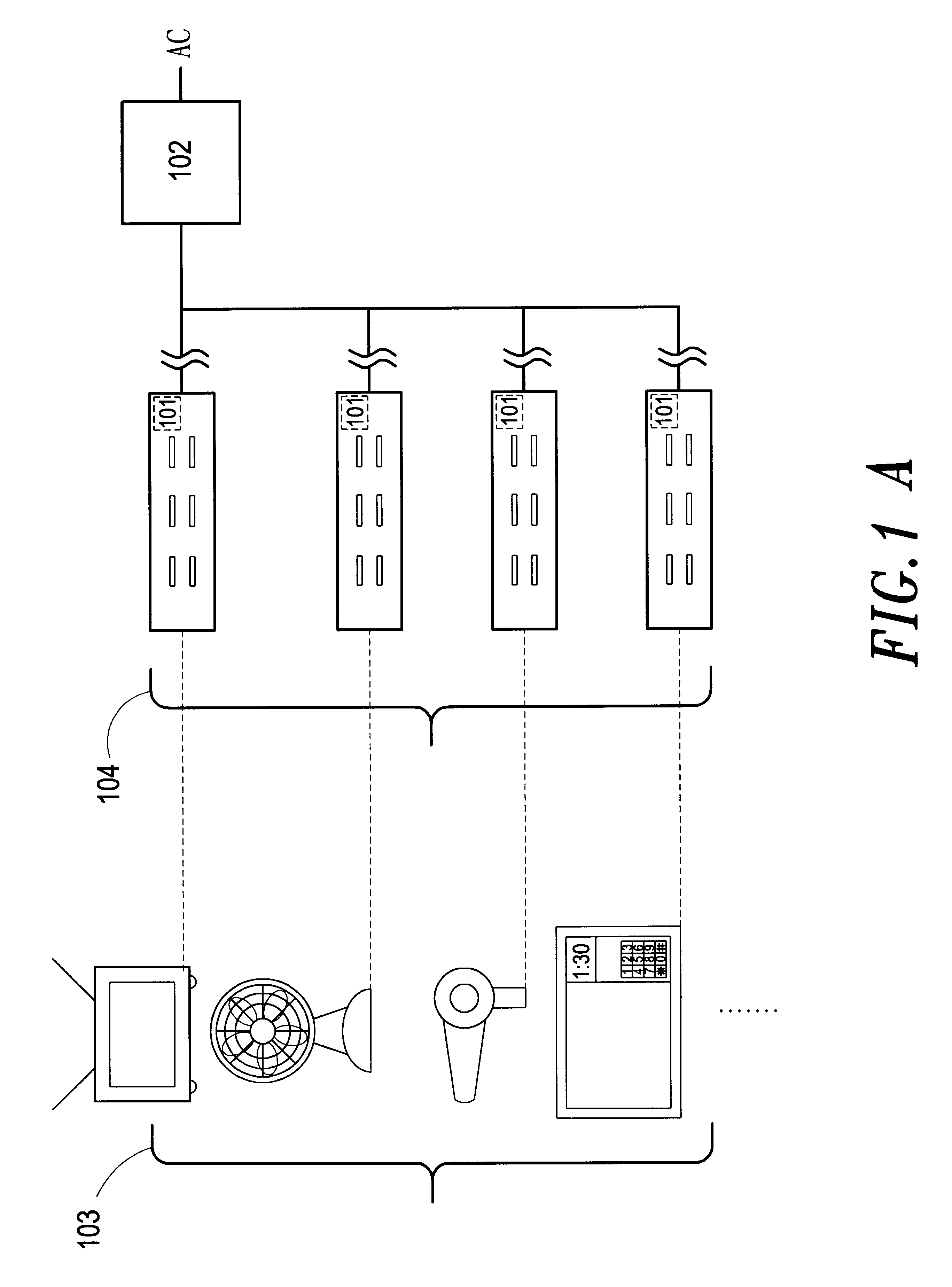
Referring to FIG. 1A, which is the schematic diagram of the power lock device for safe power output / input provided from the present invention, with the coded circuit in the power receiving end 101 and the decoded circuit in the power supply end 102, the power lock device controls if alternating current is transmitted to the power receiving end 101 of the socket 104 and supply every electric appliances 103 for operation. For application, a power supply end can be connected with several power receiving ends such that control of different groups can be achieved. Besides, a power adaptor containing an input end and an output end can be made from the present invention.

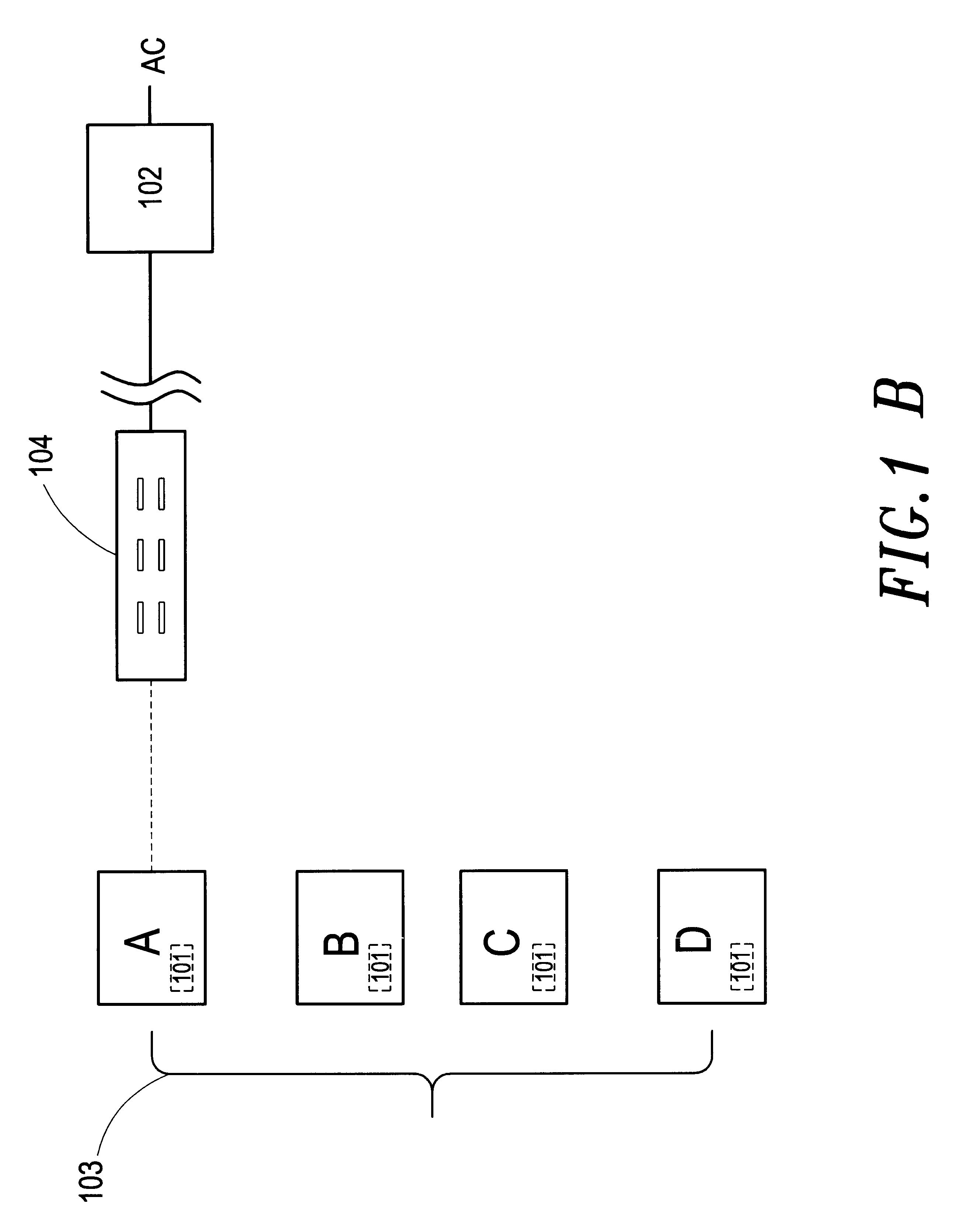
Referring to FIG. 1B, which is the other schematic diagram of the power lock device for safe power output / input provided from the present invention, the power receiving end 101 can be set inside the electric appliance 103 directly such that control of usage of the electric appliance 103 can be achieved.

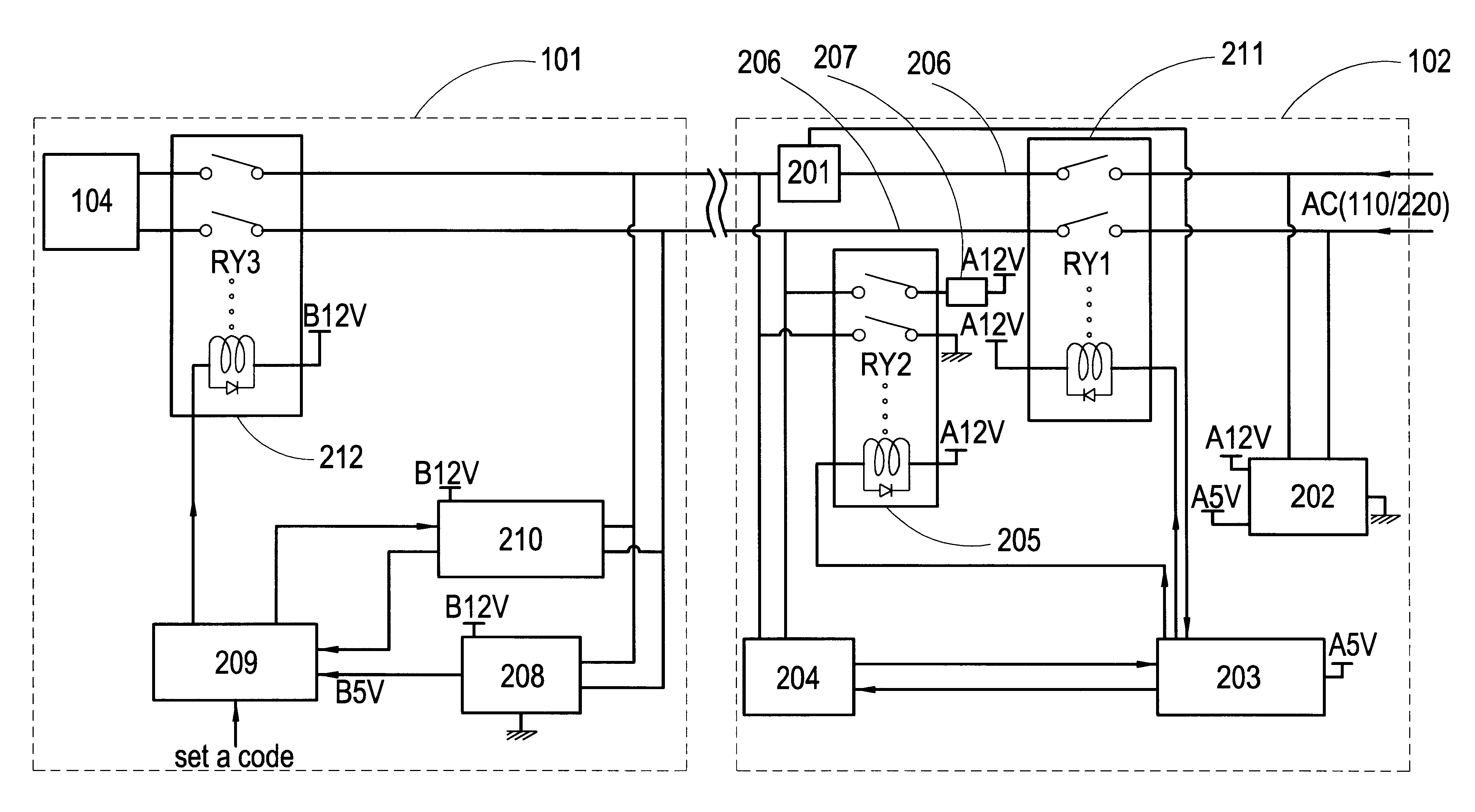
Referring to FIG. 2, ...


PUM


Abstract

A power lock device for safe power output/input is a control lock composed of coding devices, decoding devices and electromagnetic switches. The coded signal will attach to the power transmitting line and keeps on transmitting. After discerning that the coded signal is correct, the decoding device turns on electromagnetic switches and conducts power to transmit. If the code is not correct, the decoding device uses the electromagnetic switches to cut off power and achieves the function of power control.

Description

BACKGROUND OF THE INVENTION1. Field of the InventionThe present invention relates to a power lock device for safe power source output / input. The device is a control lock using coded signals attached to the power line, and is a power lock for safe power source output / input which can avoid the accident of an electric shock resulted form moving an electric appliance haphazardly and carelessly insert an electric conduct into a socket.2. Description of the Prior ArtThe commonly seen power outlets, whereon several sockets have the only function of providing power, are set up at many places in a house. Sometimes, some sockets are not used and are very possible to become the origin of accident.For the reason, the commonly seen power lock device, such as Taiwan Patent 306704 (hereafter, the cited case), is invented. The main characteristics of the commonly seen power lock device are: a power outlet which can receive power and is set on the wall or a positioned object, several sockets thereon...

Claims


Application Information

Patent Timeline
Patent Type & Authority Patents(United States)
IPC IPC(8): H02J13/00
CPCH02J13/002Y02E60/7815Y04S40/121H02J13/00007Y02E60/00
Inventor HUANG, MIN-HUANGCHANG, HER-LIN
Owner DIGIPOWER MFG
Why Eureka
Try Eureka