Cable lock assembly

a technology of cable locks and components, applied in the field of cable locks, can solve the problems of still being stolen or moved by computers

Inactive Publication Date: 2003-09-23
HSU CHING SHU
View PDF12 Cites 65 Cited by
  • Summary
  • Abstract
  • Description
  • Claims
  • Application Information

AI Technical Summary

Problems solved by technology

If the cords (80) are cut off or pulled out from the computer, the computer can still be stolen or moved.

Method used


Image

  • Cable lock assembly
  • Cable lock assembly
  • Cable lock assembly

Examples


Embodiment Construction

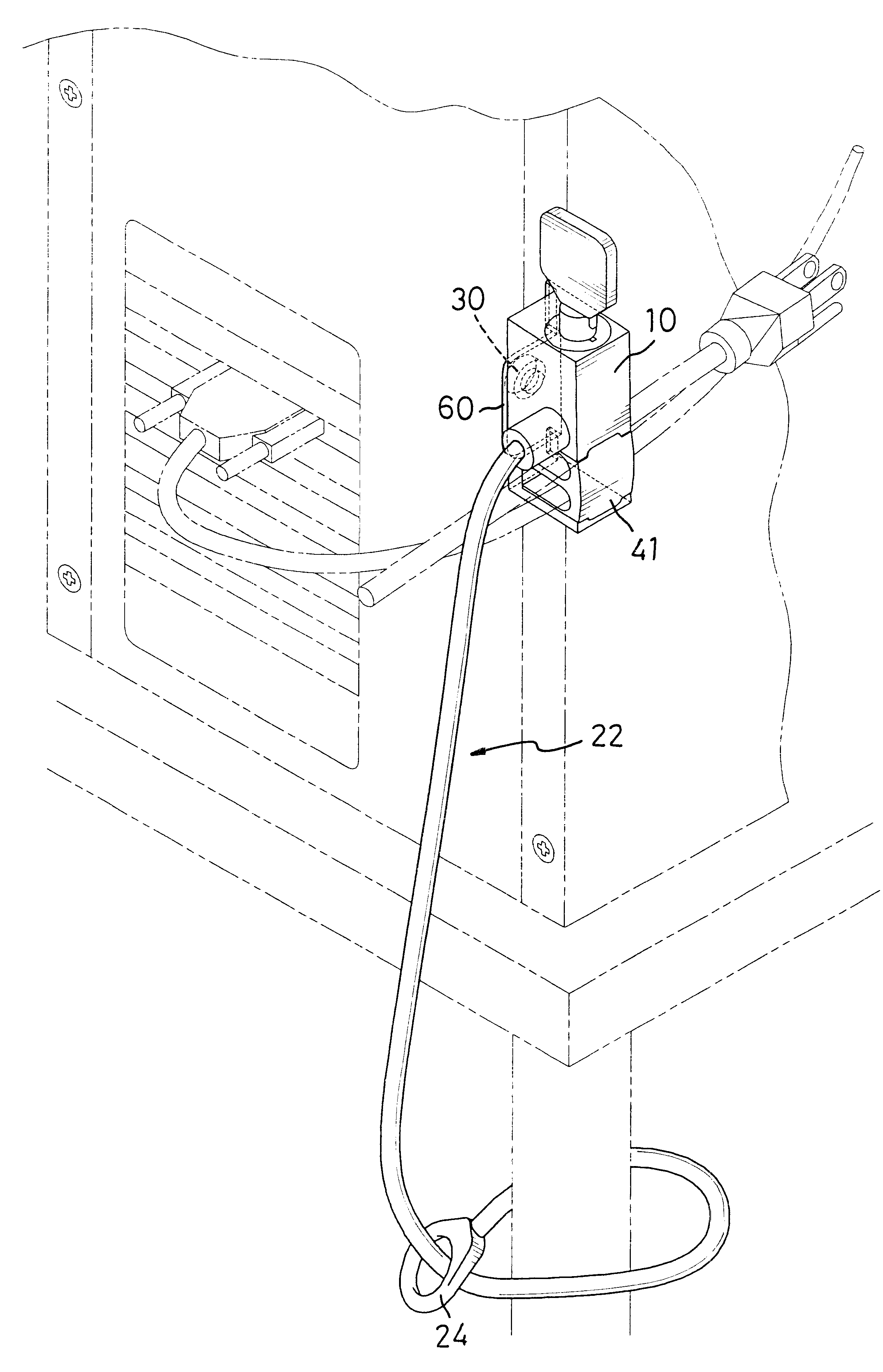
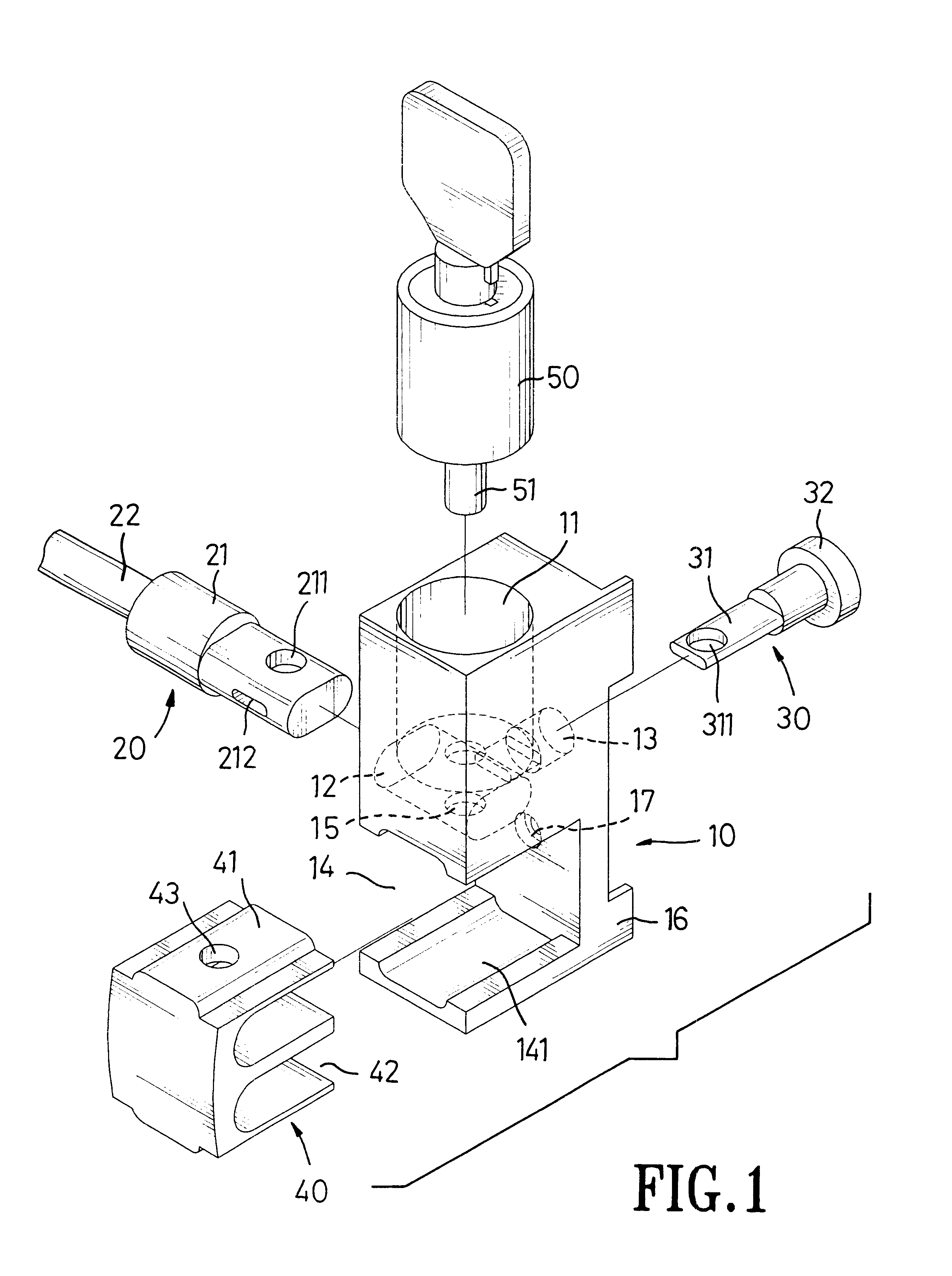
With reference to FIGS. 1 and 2, a cable lock assembly in accordance with the present invention comprises a base (10), a cylinder (50), a cable (22) and a cord holder (40). The base (10) is adapted to be attached to a computer. Two ears (16) extend outward from an edge of the base (10) and are adapted to abut a side of the computer to keep the base (10) from rotating relative to the computer.

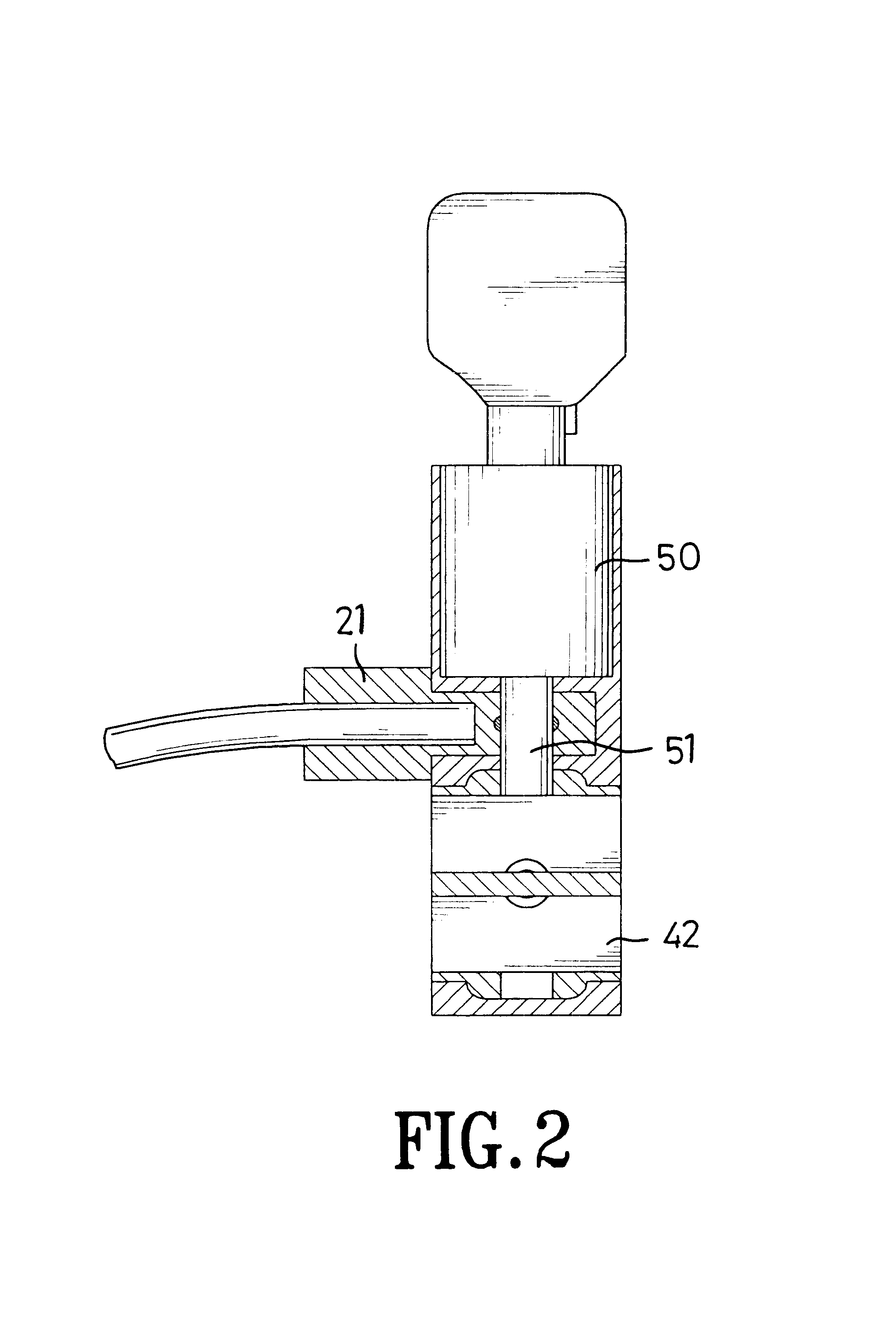
The cylinder (50) is received in a longitudinal hole (11) defined in the top of the base (10). The cylinder (50) has a lock post (51), a lock unit (not shown) and a keyhole. The lock post (51) is retractably mounted on the cylinder (50) at the end extending into the base (10). The lock unit is mounted in the cylinder (50) to lock or unlock the lock post (51). The keyhole is defined in the other end of the cylinder (50) apart from the lock post (51) and receives a key. Consequently, the user can lock or unlock the lock post (51) by the key and the lock unit.

The cable (22) is detachably connected ...


PUM


Abstract

A cable lock assembly has a base, a cylinder, a cable and a cord holder. The base is adapted to be attached to the computer with a fastener. The cylinder is mounted on the base and has a lock unit, a keyhole and a lock post. The cable is detachably connected to the base with one end and locked by the lock post. The other end of the cable is used to loop around an object. The cord holder is detachably attached to the base and locked by the lock post to hold the cords of the computer. Consequently, the computer can be locked to an object with the cable lock assembly. The computer will not be stolen or inappropriately moved even if the cords of the computer are cut off or are pulled out from the computer.

Description

1. Field of the InventionThe present invention relates to a cable lock assembly, and more particularly to cable lock assembly for a computer.2. Description of Related ArtTo prevent theft or unauthorized removal of a computer it is common to fit a cable lock to a computer to secure the computer to an object such as a desk. With reference to FIG. 6, a conventional cable lock (70) in accordance with the prior art comprises two half bodies (71,72), a lock device (not shown) and a cable (74). The half bodies (71,72) are engaged with each other. Multiple passages (73) are defined between the half bodies (71,72) for cords (80) connected to the computer and the cable (74) extending through the passages (73). Wherein, the cords (80) are used to connect the computer to an electrical power source. The lock device is mounted between the half bodies (71,72) to keep the half bodies (71,72) from being separated from each other. The cable (74) extends through one of the passages (73) and loops arou...

Claims


Application Information

Patent Timeline
Patent Type & Authority Patents(United States)
IPC IPC(8): E05B73/00G06F1/18
CPCE05B73/0082G06F1/181E05B73/0005G06F2200/1639Y10T70/411Y10T70/409Y10T70/40Y10T70/5009
Inventor HSU, CHING-SHU
Owner HSU CHING SHU
Why Eureka
Try Eureka