Hand-held carpenters tool

a carpenter's tool and hand-held technology, applied in the field of hand-held tools, can solve problems such as the hand of the worker, and achieve the effect of replacing and removing the handle easily

Inactive Publication Date: 2005-08-11
FELICIANO PEDRO
View PDF20 Cites 67 Cited by
  • Summary
  • Abstract
  • Description
  • Claims
  • Application Information

AI Technical Summary

Benefits of technology

[0023] The tool assembly further includes a keyhole saw having opposite front and rear ends and an array of teeth extending along one longitudinal side from the front end to the rear end. The rear end of the keyhole saw is pivoted to the first end of the handle and can be rotated from a closed position to an open position. The keyhole saw is disposed substantially the cavity of the handle when the keyhole saw is in the closed position. However, the keyhole saw extends substantially parallel to the longitudinal direction of the handle when the keyhole saw is in the open position. The teeth of the keyhole saw are oriented to face into the cavity of the handle when the keyhole saw is rotated into the close position. Hence, the teeth of the keyhole saw cannot cut a worker's hand while the worker is using other parts of the tool assembly. The keyhole saw can be replaced easily merely by releasing the keyhole saw from its pivotal connection to the handle and pivotally connecting a new keyhole saw in the handle.
[0026] The tool of the subject invention may further include a rasp extending along a surface of the handle opposite to the cavity. The rasp may include an array of serrations sufficiently large to abrade a work surface, such as an edge of a sheet of gypsum board. The rasp can be removed easily from the handle and replaced when worn.

Problems solved by technology

However, a major portion of the utility knife projects out from the handle when the utility knife is in its open position.
Hence, the teeth of the keyhole saw cannot cut a worker's hand while the worker is using other parts of the tool assembly.

Method used


Image

  • Hand-held carpenters tool
  • Hand-held carpenters tool
  • Hand-held carpenters tool

Examples


Embodiment Construction

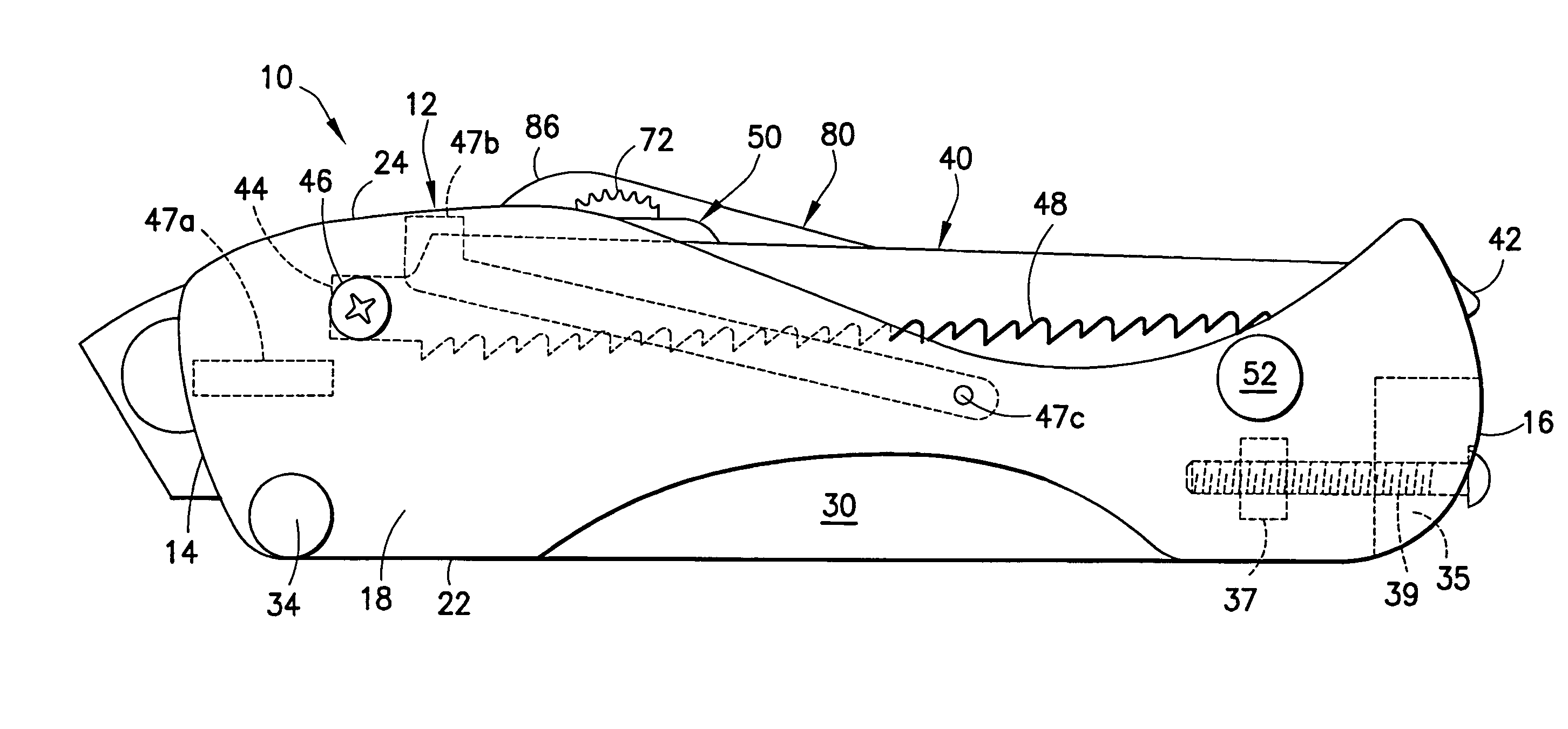
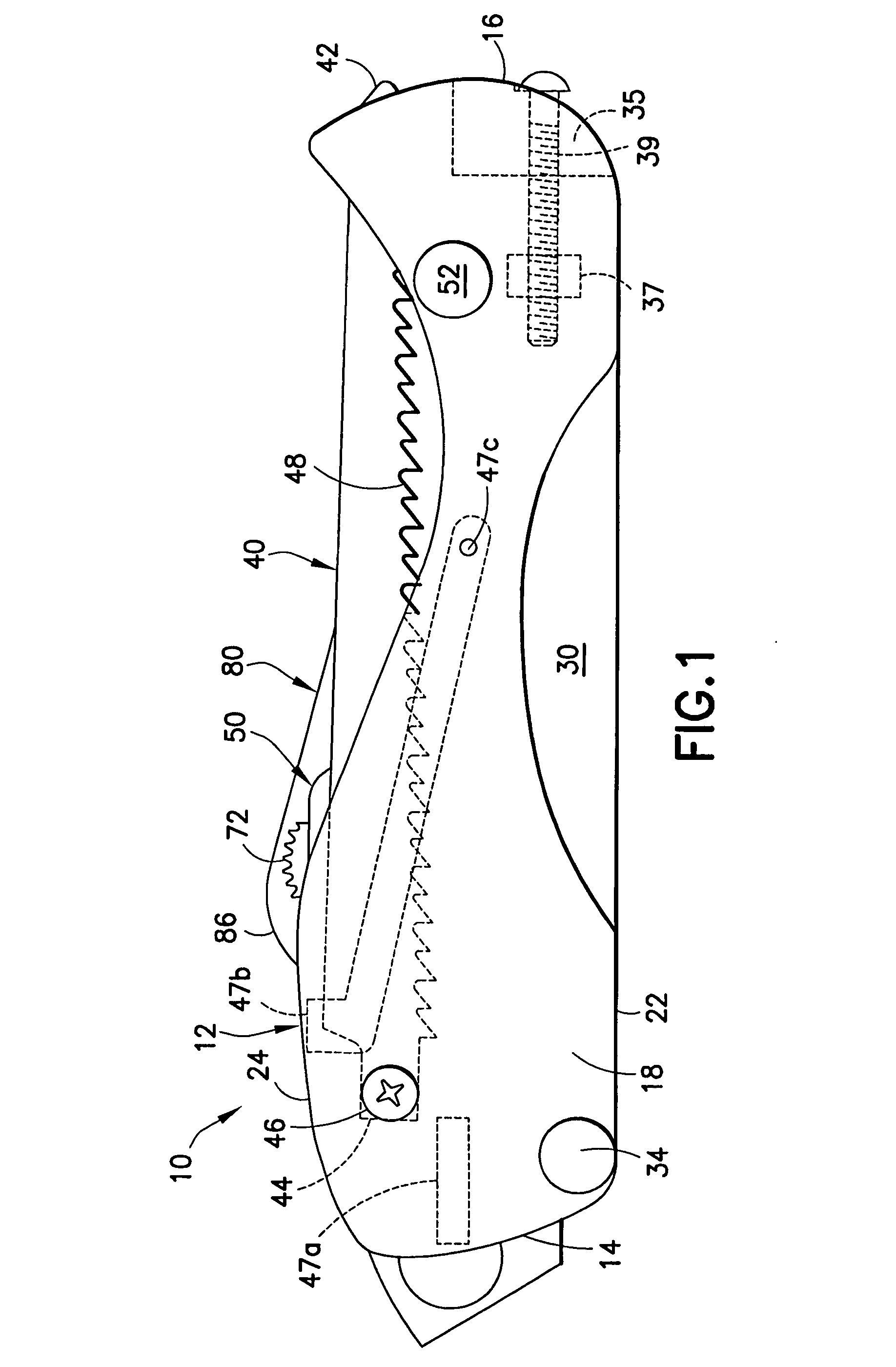
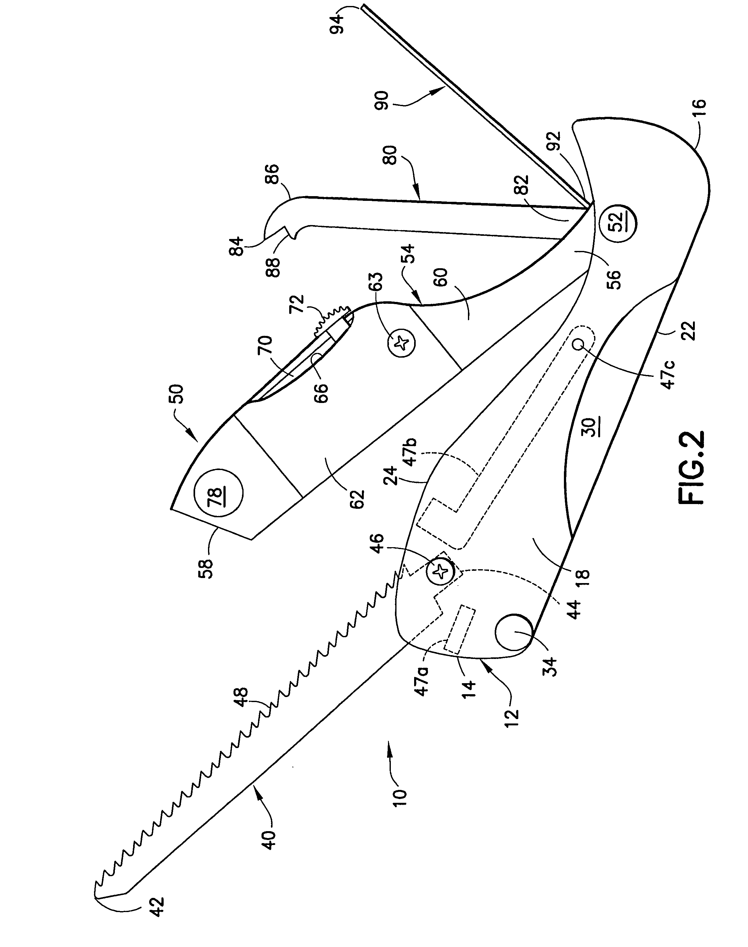
[0035] A tool assembly in accordance with the invention is identified generally by the numeral 10 in FIGS. 1-8. The tool assembly 10 includes an elongate handle 12 having a first end 14 and a rounded second end 16. The handle 12 has first and second substantially parallel sidewalls 18 and 20 that extend substantially continuously between the ends 14 and 16. The first sidewall 18 includes opposite bottom and top edges 22 and 24. Similarly, the second sidewall 20 includes opposite bottom and top edges 26 and 28. The bottom edges 22 and 26 of the sidewalls 18 and 20 respectively extend substantially linearly from the first end 14 to the second end 16 of the handle 12. However, the top edges 24 and 28 of the sidewalls 18 and 20 are curved to define a convex section near the first end 14 of the handle 12 and a concave section near the second end 16 of the handle 12. The concave sections near the second end 16 of the handle 18 facilitate access to the components of the tool assembly, as e...


PUM


Abstract

A tool assembly includes a handle and a plurality of tools mounted to the handle. Several of the tools can be rotated between a closed position and an open position relative to the handle. The tools include a utility knife, a keyhole saw, a pry bar and a punch. Additionally, the tool assembly includes a recessed rasp for trimming an edge of a sheet of gypsum board.

Description

[0001] This application claims priority on U.S. Provisional Appl. No. 60 / 543,648 filed Feb. 2004.BACKGROUND OF THE INVENTION [0002] 1. Field of the Invention [0003] The invention relates to hand held tool that can be used by a carpenter or other tradesman to perform a plurality of critical tasks easily. [0004] 2. Description of the Related Art [0005] Carpenters require convenient access to a plurality of tools for performing each of a plurality of different functions. As a result, most carpenters wear a tool belt and / or remain close to a box, bucket or bag that contains the tools the carpenter is likely to need during the course of a day. Drywall installation represents a substantial amount of the work done by many carpenters and is a task that many home improvement enthusiasts will attempt. [0006] Drywalls are formed from planar sheets of gypsum board. In particular, a gypsum slurry is formed into a substantially planar shape and secured between two sheets of a fairly sturdy paper....

Claims


Application Information

Patent Timeline
Patent Type & Authority Applications(United States)
IPC IPC(8): B25F1/04B26B5/00B26B11/00
CPCB25F1/04B26B11/00B26B5/001
Inventor FELICIANO, PEDRO
Owner FELICIANO PEDRO
Why Eureka
Try Eureka