

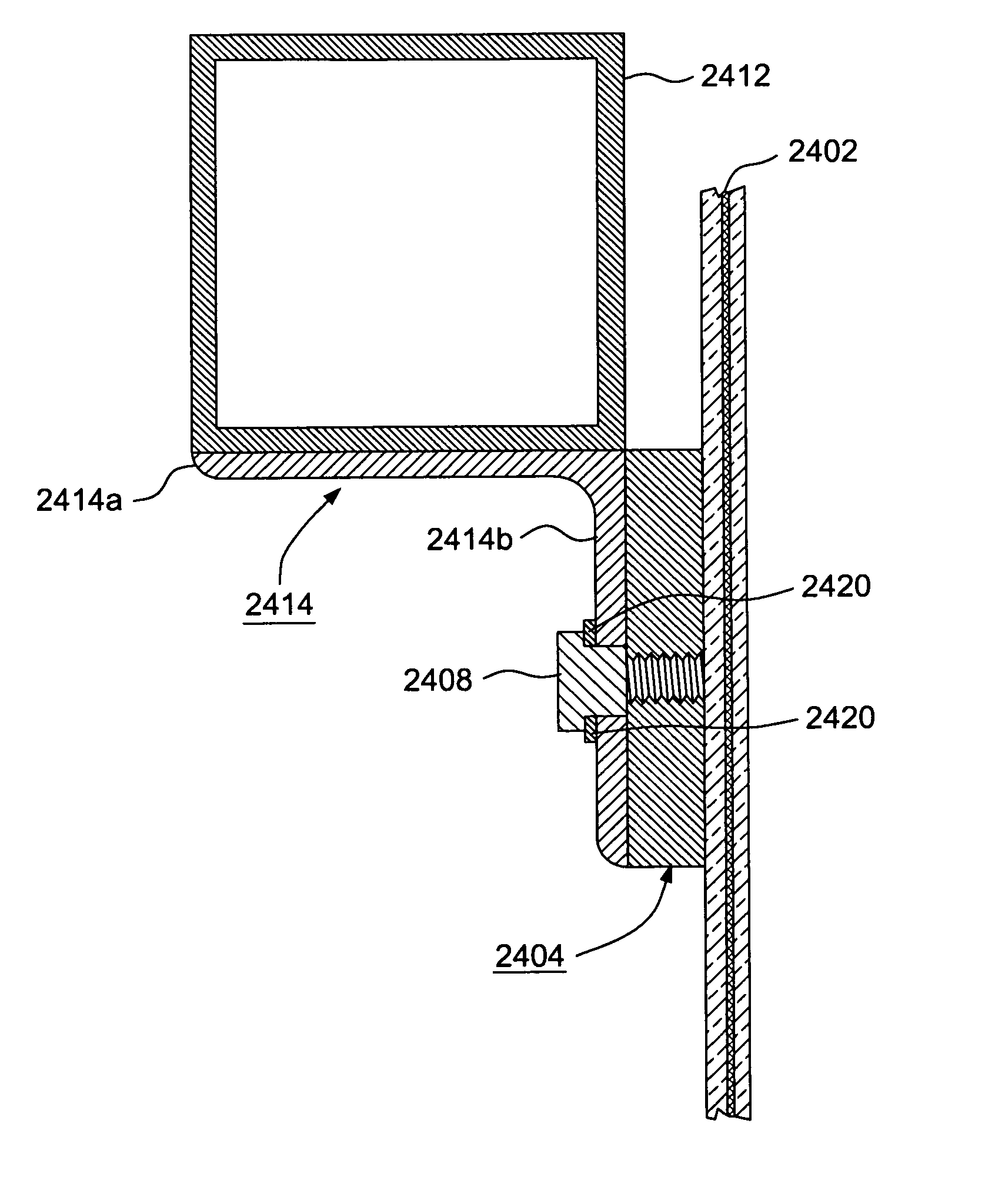
Mounting brackets for mirrors, and associated methods
a technology for mounting brackets and mirrors, applied in the field of reflectors, can solve the problems of reducing the reflective/mirror quality, de-focusing the system, and the above-mentioned process of manufacturing reflectors, and achieve the effects of increasing weight, increasing overall panel stiffness, and adding stiffness
- Summary
- Abstract
- Description
- Claims
- Application Information
AI Technical Summary
Benefits of technology
Problems solved by technology
Method used
Image

Examples
Embodiment Construction
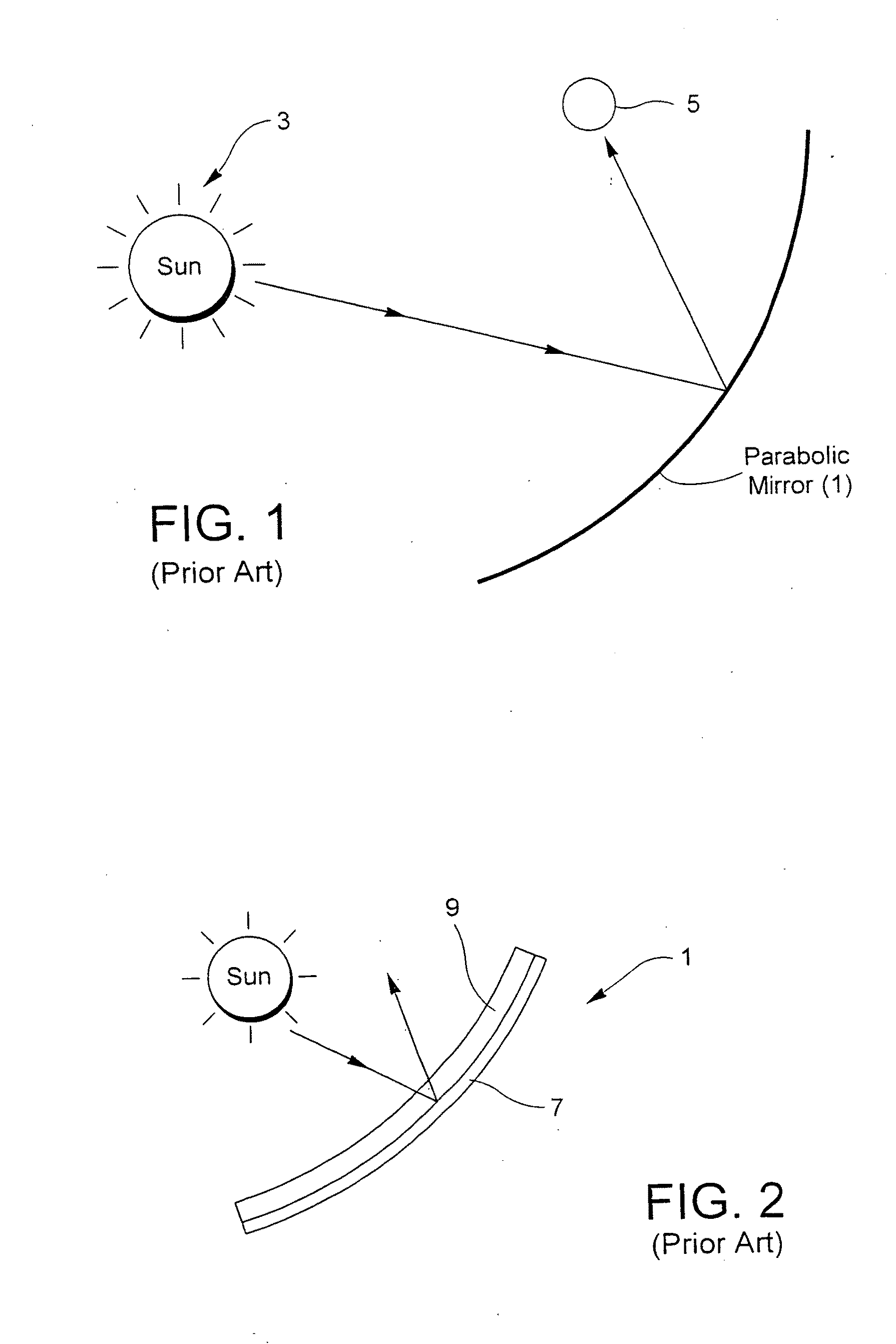
[0061]Referring now more particularly to the accompanying drawings in which like reference numerals indicate like parts throughout the several views.
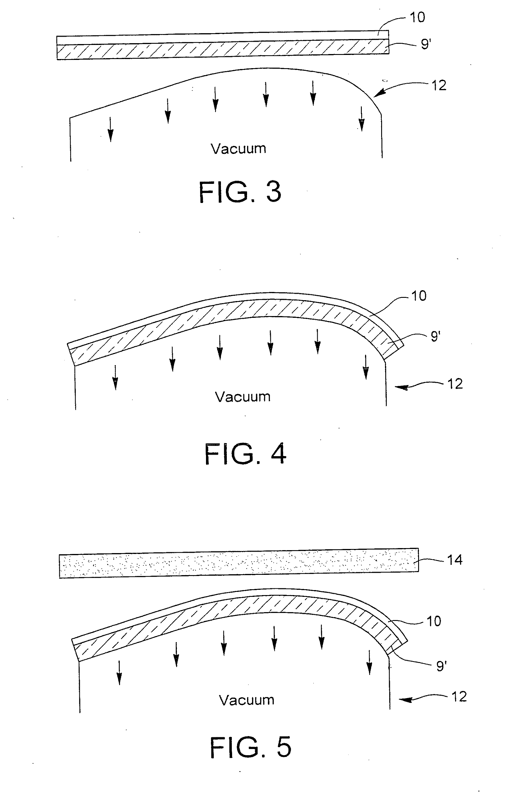
[0062]In certain example embodiments of this invention, a parabolic trough or dish reflector / mirror laminate for use in a concentrating solar power apparatus is made by: (a) forming a reflective coating on a thin substantially flat glass substrate (the thin glass substrate may or may not be pre-bent prior to the coating being applied thereto; if the thin glass substrate is pre-bent prior to application of the coating thereon then its thin nature and large size / weight will permit the glass to sag so as to be flat or substantially flat in the coating apparatus when the coating is applied thereto, such that the coating is still applied to a flat or substantially flat glass substrate even though it may have been pre-bent), (b) optionally, if the thin glass substrate in (a) was not pre-bent, cold-bending the thin glass substrate with the ref...
PUM
 Abstract
Description
Claims
Application Information