Laser welding control

a technology of laser welding and control panel, which is applied in the direction of welding apparatus, metal-working equipment, manufacturing tools, etc., can solve the problems of inability to fill the keyhole in time, the existing keyhole tends to collapse due to gravity,

Inactive Publication Date: 2006-01-19
GENERAL MOTORS COMPANY
View PDF9 Cites 73 Cited by
  • Summary
  • Abstract
  • Description
  • Claims
  • Application Information

AI Technical Summary

Benefits of technology

[0008] In the set-up of a laser welding assembly operation, workpiece material and size is selected. These selections have a significant effect on the rate of heat transfer from the weld site. For example, two overlapping pieces of aluminum alloy sheet material, each one millimeter thick, may be assembled for the formation of a weld nugget by laser beam welding. A suitable weld penetration into the aluminum sheets is then determined to obtain a desired mechanical strength for the weld.

Problems solved by technology

When the laser beam is removed (moves), the existing keyhole tends to collapse due to gravity.
In other

Method used


Image

  • Laser welding control
  • Laser welding control
  • Laser welding control

Examples


Embodiment Construction

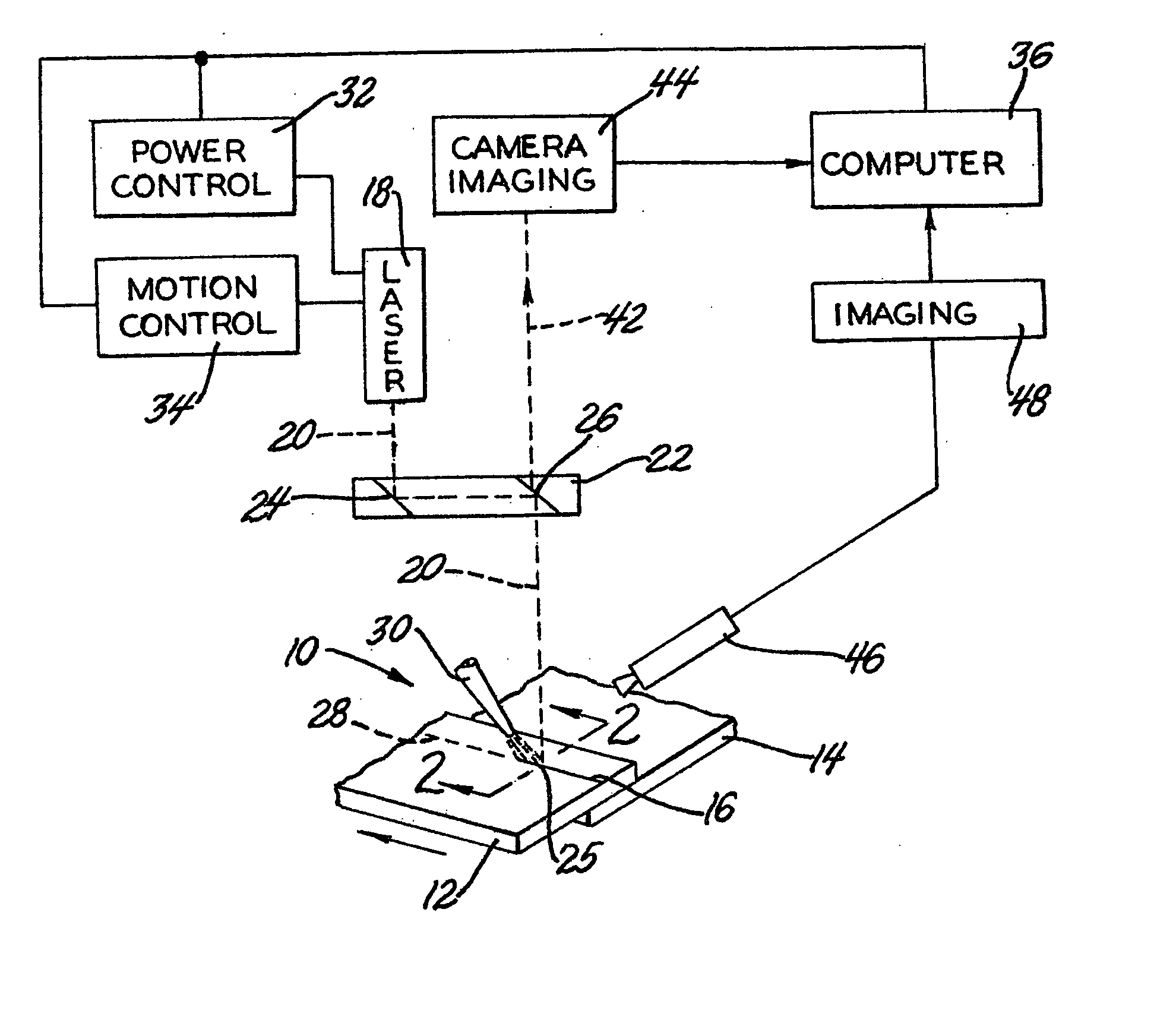
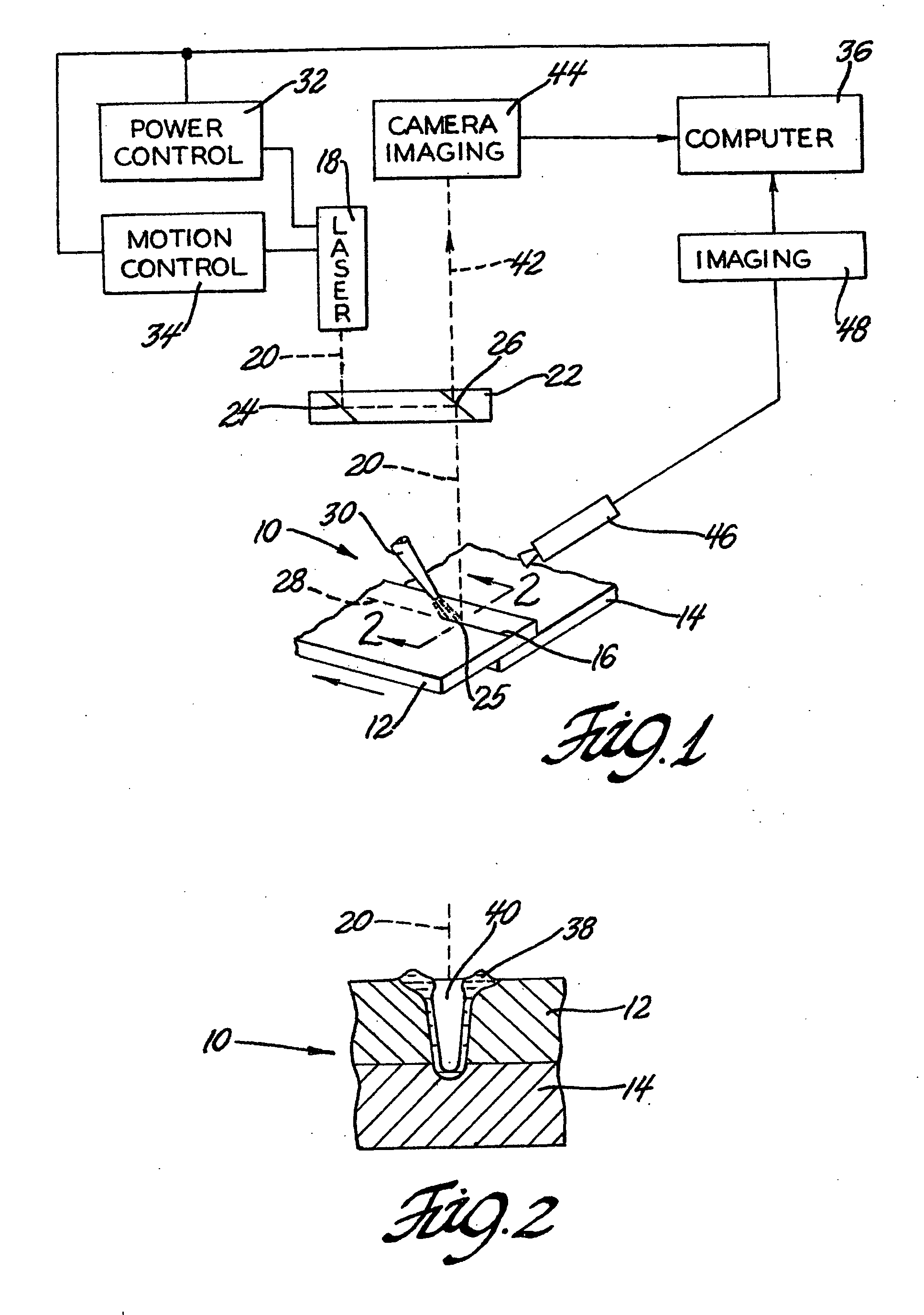
[0017] In FIG. 1 an assembly 10 of overlapping metal sheets 12, 14 is prepared for joining by laser welding. Metal sheets 12, 14, which may be sheets of aluminum alloy, are illustrated as fragments only of overlapping workpieces intended to be joined by a continuous weld seam 16.

[0018] The energy for the formation of weld seam 16 is provided by a commercial laser 18 such as, for example, a CO2 laser or an Nd:YAG laser of suitable power. In this example, a coherent high energy CO2 laser beam 20 from laser 18 is passed through an optical system 22 which redirects beam 20 at the advancing weld site 25, at the end of weld seam 16. Optical device 22 includes a first mirror 24 and a second mirror 26 for reflecting and directing of the laser beam 20.

[0019] In this welding application, laser beam 20 is continually moved in a known manner along the surface of sheet 12 in the path indicated at 28 until the weld seam 16 traverses the region of overlap of sheets 12 and 14. Also focused at the...


PUM

PropertyMeasurementUnit
Diameteraaaaaaaaaa
Widthaaaaaaaaaa
Depthaaaaaaaaaa

Abstract

In laser welding of metallic workpieces, the energetic beam is moved over the workpiece surface to form a pool of molten weld metal that quickly solidifies behind the advance of the laser into a weld nugget. The laser beam produces a keyhole of plasma-containing vapor within the molten pool. Weld nugget porosity, due to entrapment of the vapor, is minimized by continually sensing radiation from the molten metal pool to determine pool depth and width and then controlling laser power and speed to continually produce a weld metal pool wide enough for the liquid to fully expel the vapor and solidify into a pore free nugget.

Description

TECHNICAL FIELD [0001] This invention pertains to control of laser welding power, focal point and the speed of advancement of a laser welding beam to produce pore free welds. More specifically, this invention pertains to sensing and determining the depth and width of the molten weld metal pool produced by the laser beam for such welding control. BACKGROUND OF THE INVENTION [0002] The use of laser welding in the manufacture of automotive vehicle bodies and components offers higher process speeds, better precision of weld location and smaller heat affected zones. A powerful laser beam can be accurately focused on the surface of a metal workpiece and moved in a predetermined weld path to continuously form a molten pool of weld metal that re-solidifies to a weld nugget. For example, CO2 and Nd:YAG lasers have been used in these applications. In automobile manufacturing ferrous or aluminum alloy parts are joined by this practice. [0003] The highly coherent, focused and energetic laser be...

Claims


Application Information

Patent Timeline
IPC IPC(8): B23K26/24B23K26/03
CPCB23K26/032B23K26/246B23K26/123B23K26/034B23K26/244
Inventor WANG, PEI-CHUNGTSAI, HAI-LUNGHUANG, YUEH-SE J.TURNER, PHILLIP M.
Owner GENERAL MOTORS COMPANY
Why Eureka
Try Eureka