Coplanar directional coupler for hybrid geometry

a technology of coplanar directional coupler and hybrid geometry, which is applied in the direction of multiple-port network, electrical apparatus, waveguide, etc., can solve the problems of over-tuned process, variable coupling factor, and coupler taking up to fifteen minutes to tune correctly

Inactive Publication Date: 2003-09-23
RADIO FREQUENCY SYST
View PDF37 Cites 12 Cited by
  • Summary
  • Abstract
  • Description
  • Claims
  • Application Information

AI Technical Summary

Benefits of technology

When designed for a particular application specified by the coupling factor, directivity, and frequency range, the coplanar coupler of the present invention does not require further tuning. This eliminates the effort in including additional tuning mechanisms during manufacture of the coupler. The ability to precisely design the coupler also eliminates tuning during installation. The coupler also has a compact size compared to known coupler arrangements. The present invention further takes into consideration that the coupling and directivity properties of the designed coplanar coupler may deviate slightly from design parameters to due different manufacturing tolerances in constructing the housing for the main transmission line, for example, as well as electrical tolerances for component resistors and components of the RF sub-systems in which the coupler is used. Therefore, as an additional feature of the present invention, the coupling factor may be fine-tuned by adjusting a tuning screw.

Problems solved by technology

The above tuning process to position the coupler to achieve the target directivity and degree of coupling takes a significant amount of time and effort.
Specifically, rotational adjustments for directivity commonly cause variation in the coupling factor and vice versa.
Due to these difficulties, a coupler can take up to fifteen minutes to tune correctly.
Additionally, due to the number of components that must be hand-assembled, such as the cup, the resistor, coupling wire and connector, the known coupler is also expensive to manufacture, and has a bulky configuration.

Method used


Image

  • Coplanar directional coupler for hybrid geometry
  • Coplanar directional coupler for hybrid geometry
  • Coplanar directional coupler for hybrid geometry

Examples


first embodiment

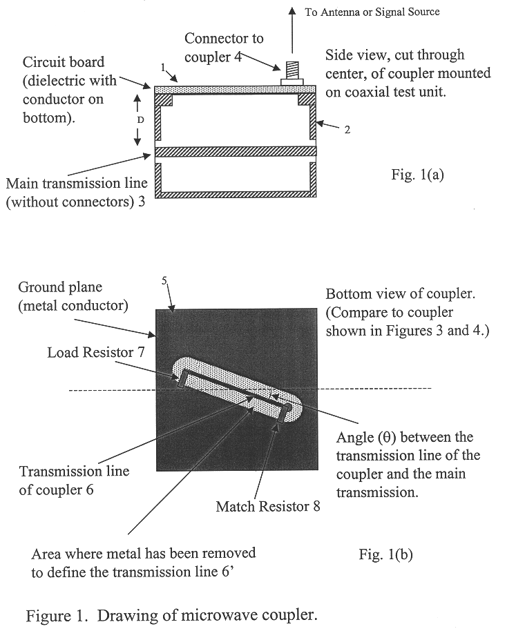
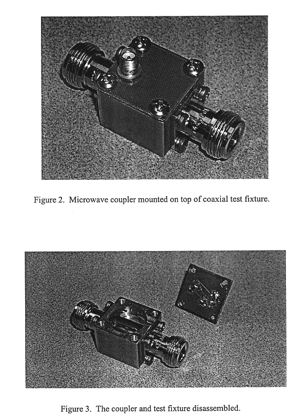
FIG. 1(a) illustrates a planar coupler 1 according to the invention, assembled with a housing 2 and a main transmission line 3. A connector 4 connects the coupler with a measurement device or other RF sub-system. The coupler includes a printed circuit board, with a conductor provided on the plane facing the transmission line 3, and a dielectric on the other plane of the board substrate. Copper may be used as a standard conductor material, but other conducting materials may be used. The housing 2 is designed with a distance D between the transmission line 3 and the bottom face of the coupler to provide a specified coupling factor.

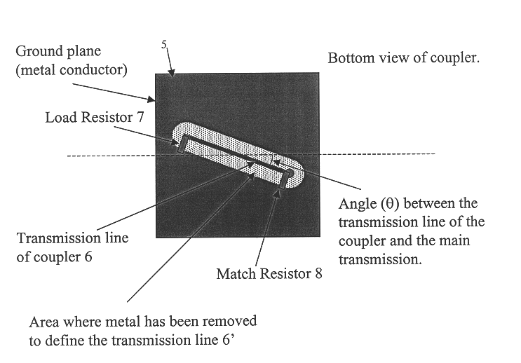
Referring to FIG. 1(b), the microwave coupler includes a planar circuit 5 on which a coupling transmission line 6 has been described. The transmission line 6 merely comprises a part of the conductive plate, from which a portion of the conductive material has been removed 6'. The line 6 may be formed by mechanical milling or by chemical wet etch. One skilled ...

second embodiment

Description of Second Embodiment

Despite the selection of an appropriate angle .theta., displacement D (or d') and resistor values, tuning may be required for instances where the specified tolerances cannot be achieved without tuning due to the mechanical tolerances of the fabrication of the planar coupler structure or the housing, and the electrical tolerances of the main transmission line, the resistor(s) and other RF subsystems connected to the coupler structure. The need for tuning will be determined by the acceptable coupler tolerances for each particular application. For precise coupling requirements, such as .+-.0.5 dB, tuning is likely to be required. For less stringent design requirements, such as .+-.2 dB, the tuning structure may not be necessary.

FIG. 6 shows the additional tuning screw protruding through the sidewall of the trough that contains the main transmission line. The tuning screw is positioned such that, when it advances into the trough of the main transmission l...

third embodiment

Description of Third Embodiment

To further reduce assembly costs for the coupler, the present inventors determined that the preferred embodiment can be modified to include only a single resistor for satisfactory operation.

The prototype coupler of FIG. 6 uses only one resistor (the load resistor 7, seen as the small, black rectangle at the end of the center coplanar line) and still achieves more than 20 dB of directivity with a coupling of 50 dB. The second resistor may be eliminated from the prototype design presented by the proper choice of coplanar transmission line dimensions and load resistor (FIG. 1(b), 7) value. Resistor 8 may still be necessary in some designs where the coplanar dimensions are limited because of the coupling values required and / or because of the geometry of the main transmission line.

For the coupler design including a single resistor, a resistor value of 50 ohms and an angle .theta. of 45 degrees provided a coupling factor of 50 dB, and a directivity of 30 dB....


PUM


Abstract

A microwave coupler has a planar form with a transmission line segment oriented at an angle relative to a main transmission line. The planar form of the transmission line, such as in a printed circuit board, helps reduce the size and manufacturing costs for the coupler. When placed a prescribed distance from the main transmission line and oriented at an appropriate angle, the directivity and coupling factor requirements can be met precisely with minimal tuning. Where fine tuning is required, a tuning screw and resistor disposed adjacent to the transmission line segment are provided.

Description

The present invention relates to a directional coupler with a high degree of directivity and compact size to facilitate assembly of the coupler and installation of the coupler within a communication system.Description of Related ArtA photograph of a previously known microwave coupler is shown in FIG. 8. The coupler includes a cup-shaped holder with a resistor and a coupling loop disposed on the large-sized opening of the cup. A connector on the back side of the cup is connected to a measurement system or any external circuit. The cup-shaped coupler is disposed in a housing in proximity to a main transmission line. More particularly, the broad opening is disposed to face a main transmission line, and the cup is rotated relative to the transmission line to control the directivity of the coupling and is positioned within the housing closer to or away from the transmission line to control the degree of coupling.The above tuning process to position the coupler to achieve the target direc...

Claims


Application Information

Patent Timeline
Patent Type & Authority Patents(United States)
IPC IPC(8): H01P5/16H01P5/18
CPCH01P5/184
Inventor WANG, CHIWILBER, WILLIAM D.
Owner RADIO FREQUENCY SYST
Why Eureka
Try Eureka