Electromagnetic valve drive apparatus of internal combustion engine

a technology of electromagnetic valve and drive apparatus, which is applied in the direction of non-mechanical valves, electrical control, machines/engines, etc., can solve the problems of increasing the size and the cost of electromagnetic valve drive apparatus, increasing the number of switching elements employed, and allowing for more complicated control of current through electromagnetic coils

Inactive Publication Date: 2003-09-30
TOYOTA JIDOSHA KK
View PDF15 Cites 21 Cited by
  • Summary
  • Abstract
  • Description
  • Claims
  • Application Information

AI Technical Summary

Problems solved by technology

Therefore, in the case of a four-cylinder four-valve engine, 128 switching elements are needed for the 16 valves, thus leading to a size increase and a cost increase of the electromagnetic valve drive apparatus.
However, even with the sharing of switching elements, the total number of switching elements employed is still large.
However, due to the provision of the mechanism for holding the valves in the closed state without using electromagnetic force, it may necessary to drive a switching element during the closed valve period.
Therefore, it becomes possible to perform a more complicated control of current through the electromagnetic coils.

Method used


Image

  • Electromagnetic valve drive apparatus of internal combustion engine
  • Electromagnetic valve drive apparatus of internal combustion engine
  • Electromagnetic valve drive apparatus of internal combustion engine

Examples


reference example 1

differs from embodiments of the present invention in that Reference Example 1 employs two drive circuits 3592a, and 3592b illustrated in FIGS. 67 and 68 in place of the drive circuit 3192a. Similarly, the other drive circuits 3192b-3192d in are replaced by combinations of two of drive circuits 3592c, 3592d, 3592e, 3592f, 3592g, and 3592h that have basically the same construction as the drive circuits 3592a, and 3592b. Therefore, the drive circuits 3592a, and 3592b will be described below as representatives of the other drive circuits. Other configurations of Reference Example 1 are substantially the same as those of the previous embodiments, unless otherwise noted.

The drive circuit 3592a depicted in FIG. 67 is provided with 10 FETs as switching elements 3500, 3502, 3504, 3506, 3508, 3510, 3512, 3514, 3516, and 3518. Of the switching elements, two switching elements 3500, and 3502 are connected in series, and are disposed between a high potential side terminal 3541a and a low potenti...

embodiment 1

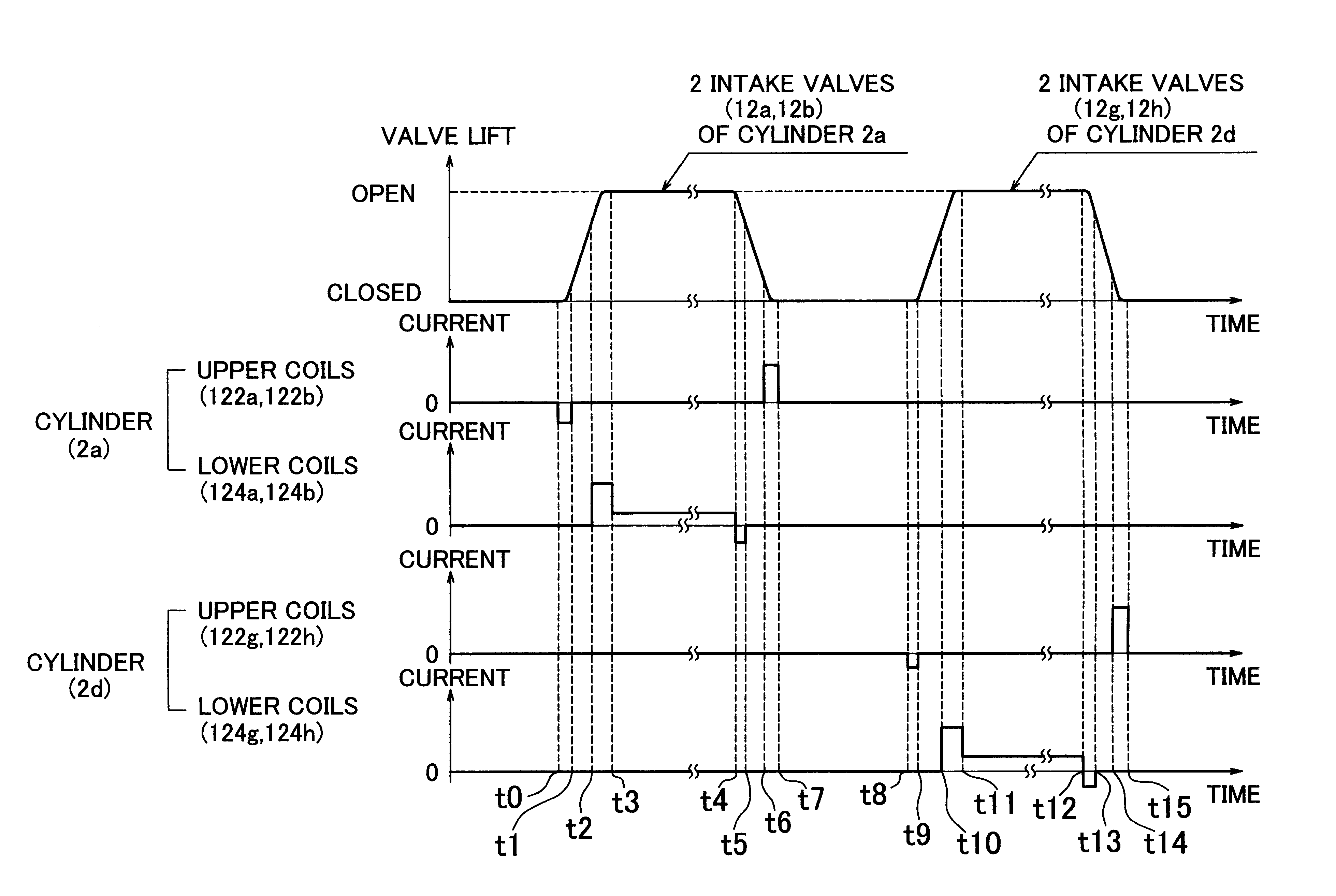
FIGS. 70A1 to 70P2 are circuit diagrams indicating states of control performed on the drive circuits 3592a, and 3592b depicted in FIGS. 67 and 68 to realize the operations indicated in FIG. 69. In FIGS. 70A1 to 70P2, the conductive wires 3552-3561 are omitted. Furthermore, in FIGS. 70A1 to 70P2, broken line arrows and circles ".quadrature." indicate the same states as described above in conjunction with

It is assumed that before a time point t240 indicated in FIG. 69, the armatures 110 are brought into contact with the upper cores 116 as depicted in FIG. 10 by temporary excitation of the upper coils 3622a, 3622b, 3622g, and 3622h, and that this contact state is maintained by the magnetic attraction forces of the upper magnets 116d. Therefore, the valve bodies 100 are in contact with the valve seats 126. Thus the two intake valves of the first cylinder and the two intake valves of the fourth cylinder are in a completely closed state. The OFF signals are outputted to all the 20 switchi...


PUM


Abstract

An electromagnetic valve drive apparatus of an internal combustion engine has a three-switching element in-series type drive circuit. Through switching operations of switching elements that are shared by eight electromagnetic coils consisting of upper coils and lower coils of four valves. The four valves include a first two valves that perform identical operations and a second two valves whose open period does not overlap the open period of the first two valves. The three-switching element in-series type drive circuit is able to supply current and to rapidly reduce, or discontinue, current through the electromagnetic coils. The electromagnetic valve drive apparatus is able to control the quantity of current through the electromagnetic coils while reducing the number of switching elements employed.

Description

1. Field of the InventionThe invention relates to an electromagnetic valve drive apparatus of an internal combustion engine and, more particularly, to an internal combustion engine electromagnetic valve drive apparatus in which intake valves and / or exhaust valves provide for a plurality of cylinders with valve-opening electromagnetic valves, valve-closing electromagnetic valves, and closed valve state holding mechanisms that do not employ electromagnetic force, and in which drive circuits are provided for the electromagnetic valves, whereby the valves are opened and closed.2. Description of the Related ArtThe disclosure of Japanese Patent Application No. HEI 11-347396 filed on Dec. 7, 1999 is herein incorporated by reference.Known electric valves are used as intake valves or exhaust valves of internal combustion engines. An example of electromagnetic valves an armature displaceable with a valve body, a pair of electromagnetic coils disposed above and below the armature, and springs ...

Claims


Application Information

Patent Timeline
Patent Type & Authority Patents(United States)
IPC IPC(8): F02D41/20F01L9/00F02D13/02F01L9/04F16K31/06
CPCF02D13/0207F02D13/0253F02D41/20F02D13/0261F02D2041/001F02D2041/2072F02D2041/2079F02D2041/2082Y02T10/18Y02T10/12F01L9/00
Inventor YANAI, AKIHIROMAKITA, MITSUGU
Owner TOYOTA JIDOSHA KK
Why Eureka
Try Eureka