Safety syringe

a safety syringe and syringe technology, applied in the field of safety syringes, to achieve the effect of difficult forcible extraction and difficult engagemen

Inactive Publication Date: 2003-09-30
NUSAF
View PDF91 Cites 62 Cited by
  • Summary
  • Abstract
  • Description
  • Claims
  • Application Information

AI Technical Summary

Benefits of technology

In another preferred embodiment, the plunger and the barrel are designed to lockingly engage one another when the plunger is fully depressed, preventing the plunger from being extracted. This will secure the plunger in its fully depressed position adjacent to the diaphragm. With the plunger locked there, it will prevent the diaphragm and the sheath from being pushed back toward the plunger end of the barrel. Together with the l

Problems solved by technology

The trailing edge of the first tooth is flat and will

Method used


Image

  • Safety syringe
  • Safety syringe
  • Safety syringe

Examples


Embodiment Construction

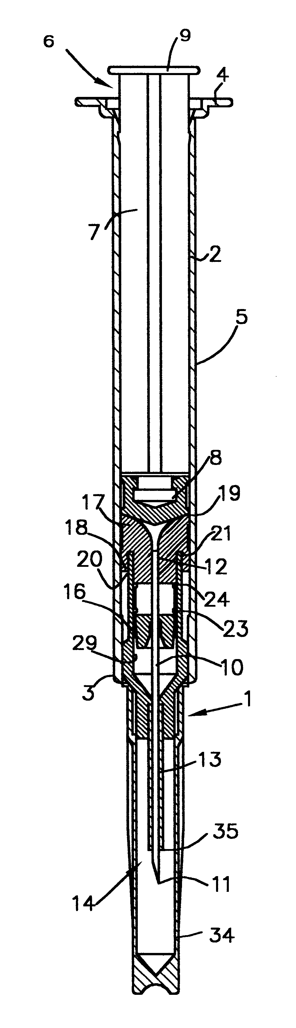
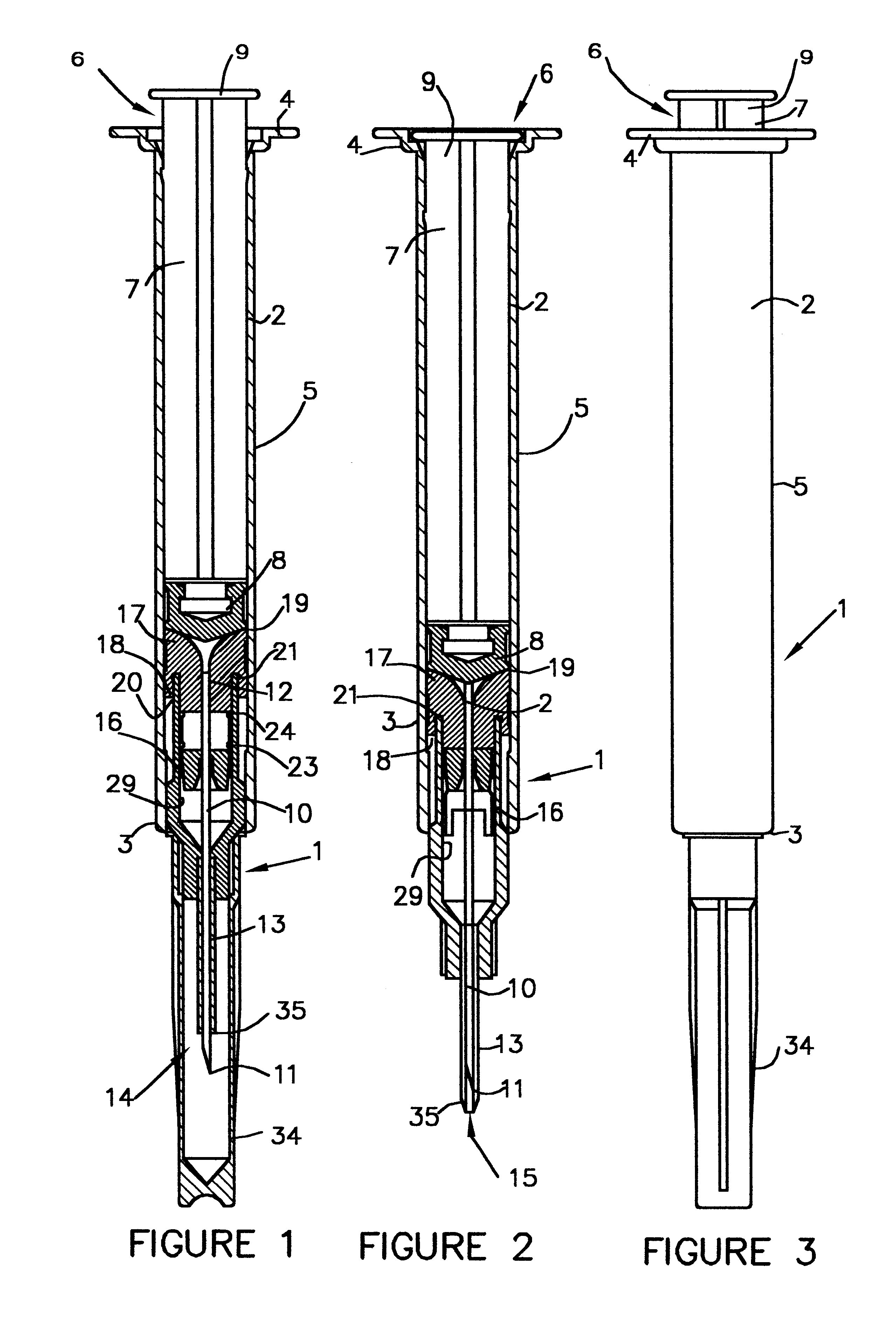
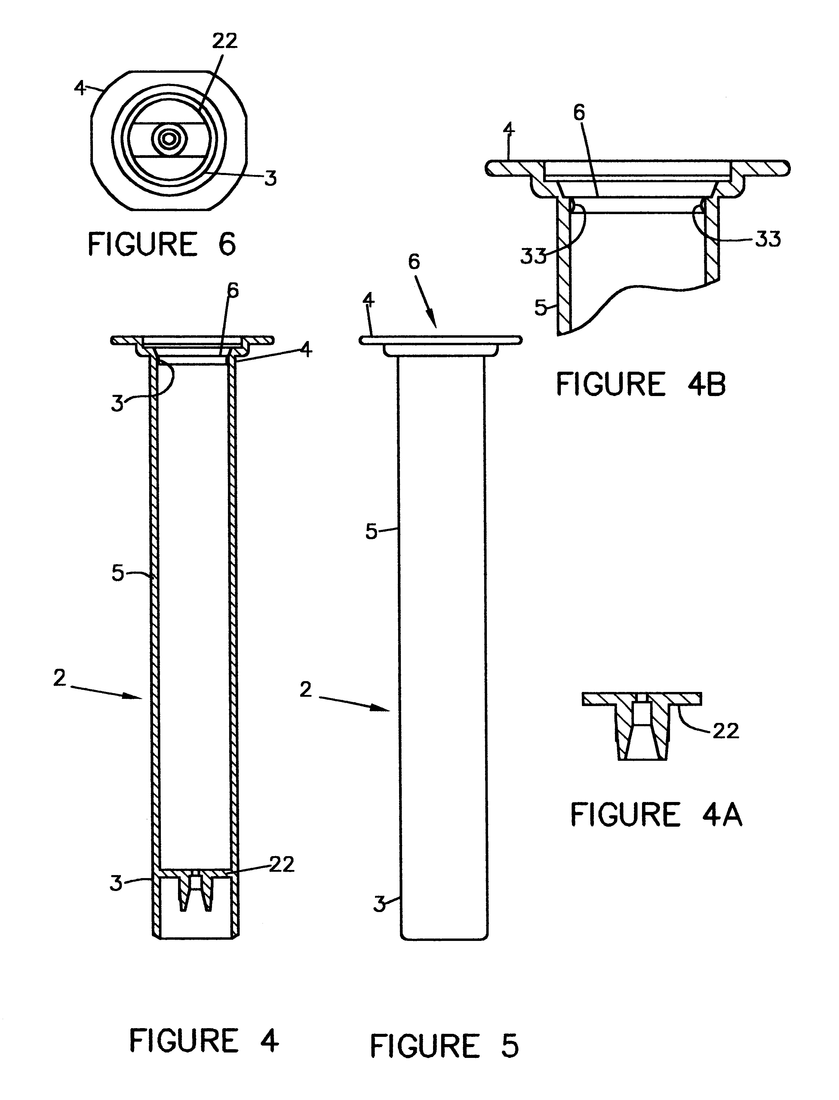
The invention comprises a safety syringe 1 comprising a barrel 2 having a needle end 3 a plunger end 4 and sides 5 extending therebetween. Plunger end 4 contains a plunger opening 6 sized to receive a plunger 7. Plunger 7 has a washer end 8 and a control end 9, and is slidably positioned in barrel 2 so that washer end 8 is initially positioned within barrel 2 and control end 9 is positioned external to barrel 2. Washer end 8 should be configured to create a substantially fluid tight seal with barrel sides 5. Washer end 8 may be made of or covered with rubber or a rubberlike plastic and coated with an FDA approved silicone or other lubricant to help in the formation of the seal between sides 5 and washer end 8 or other rubber components of syringe 1.

Plunger 7 is preferably configured so that when plunger 7 is fully depressed, plunger 7 is completely contained within barrel 2, as illustrated in FIG. 2. In this position, it is preferred that control end 9 of plunger 7 be either flush w...


PUM


Abstract

A safety syringe having a sheath advanceable into a covered position by operation of the plunger with a mechanism for securing the sheath in the covered position. A bar extends across the interior of the barrel. One or more arms depend from the sheath, engaging the plunger directly or indirectly. Depressing the plunger pushes the sheath, via the arms, into the covered position. The arms each include a first and a second tooth. As the sheath is advanced, the first tooth will encounter the bar. The leading edge of the first tooth is beveled to allow the tooth to pass over the bar. The trailing edge of the first tooth is not beveled, preventing the first tooth from being pulled back over the bar. The leading edge of the second tooth is likewise not beveled, also preventing the second tooth from passing over the bar. The first and second teeth lock the bar between them, preventing the sheath and arms from moving in either direction. Thus, the sheath will be locked in the covered position when the bar is between the teeth. Additional security is provided by locking the fully depressed plunger in the barrel. Locking the plunger in place will prevent the sheath from returning to the exposed position. Additionally, the fully depressed plunger is sized to be completely contained within the barrel, inhibiting access to the plunger and making forcible retraction of the plunger more difficult, thereby further inhibiting reuse of the syringe.

Description

BACKGROUND OF THE INVENTION1. Field of the InventionThe invention relates to safety syringes in general and to an improved locking mechanism for safety syringes in particular.2. Prior ArtIn one form of safety syringe, the sheath is advanced by operation of the plunger. Examples of these safety syringes can be found in U.S. Pat. Nos. 5,720,727 and 5,460,611, which are both hereby incorporated by reference in their entirety. Syringes of this type offer excellent protection for the health care worker from accidental needle sticks; however, an additional concern is the reuse of the needles by intravenous drug users. Reuse of needles is a significant contributing factor to the spread of blood born diseases like AIDS and hepatitis. Many prior art safety syringes have locking mechanisms which are designed to secure the syringe in the safe position. However, most of these locking systems are designed to prevent the accidental return of the needle to an exposed condition. They are not design...

Claims


Application Information

Patent Timeline
IPC IPC(8): A61M5/32A61M5/50
CPCA61M5/326A61M5/502A61M2005/3247A61M2005/3265
Inventor BERLER, BARRY
Owner NUSAF
Why Eureka
Try Eureka