Enhanced multiple injection for auto-ignition in internal combustion engines

a technology of internal combustion engine and auto-ignition, which is applied in the direction of electrical control, non-mechanical valves, instruments, etc., can solve the problems of insufficient inability to achieve sufficient mixing of air and fuel, and inability to control the burning

Inactive Publication Date: 2003-10-21
NISSAN MOTOR CO LTD
View PDF20 Cites 35 Cited by
  • Summary
  • Abstract
  • Description
  • Claims
  • Application Information

AI Technical Summary

Benefits of technology

It is another object of the present invention to provide an internal combustion engine with a fuel injection system capable of performing enhanced fuel injection that enhances engine operation on auto-ignition combustion of fuel at extended operating conditions.

Problems solved by technology

NOx emission produced in controlled auto-ignition combustion is extremely low.
Sufficient mixing of air and fuel cannot be expected if total fuel quantity becomes great.
Besides, beginning of burning is not controllably adjusted toward an appropriate crank angle around TDC of compression stroke against varying operating conditions, making it difficult to extend operation range where auto-ignition combustion can be accomplished.
Thus, expected improvement in fuel consumption rate and emission performance cannot be made.

Method used


Image

  • Enhanced multiple injection for auto-ignition in internal combustion engines
  • Enhanced multiple injection for auto-ignition in internal combustion engines
  • Enhanced multiple injection for auto-ignition in internal combustion engines

Examples


second embodiment

The second embodiment is substantially the same as the first embodiment described previously in connection with FIGS. 1 to 13. However, the second embodiment is different from the first embodiment in that injection timing IT1 and fuel quantity q1 for main injection are varied against variation of load request in addition to the variation of injection timing IT2 and fuel quantity q2 for trigger injection.

As explained before, knock intensity defines a limit of higher load operating conditions at which auto-ignition combustion is achieved. To suppress knock intensity, retarding BOB from TDC of works. As explained before in connection with FIG. 11, a retard of injection timing IT2 and an increase in fuel quantity q2 for trigger injection corresponding to the retard are required to provide a desired retard of BOB. However, as explained before in connection with FIG. 6, there is a limit to increasing fuel quantity q2 for trigger injection because heterogeneous mixture with local rich port...

third embodiment

The third embodiment is substantially the same as the first embodiment described previously in connection with FIGS. 1 to 13. However, the third embodiment is different from the first embodiment in that injection timings IT1 and T2 and fuel quantities q1 and q2 are varied against variation of load request and engine speed.

Referring to FIG. 17, the maximum rate of change dP / dtmax increases as engine speed increases as illustrated by the curve 198. This curve 198 shows that occurrence of knock is high at high engine speed. Thus, it is necessary to retard BOB from TDC of compression stroke at higher engine speeds.

FIG. 18 illustrates variation of injection timing IT2 for trigger injection against various engine speed and load request. As mentioned previously, injection timing IT2 increases in crank angle in a retard direction at higher load request. In the third embodiment, injection timing IT2 increases in crank angle in a retard direction at higher engine speeds. In FIG. 18, a number ...

fourth embodiment

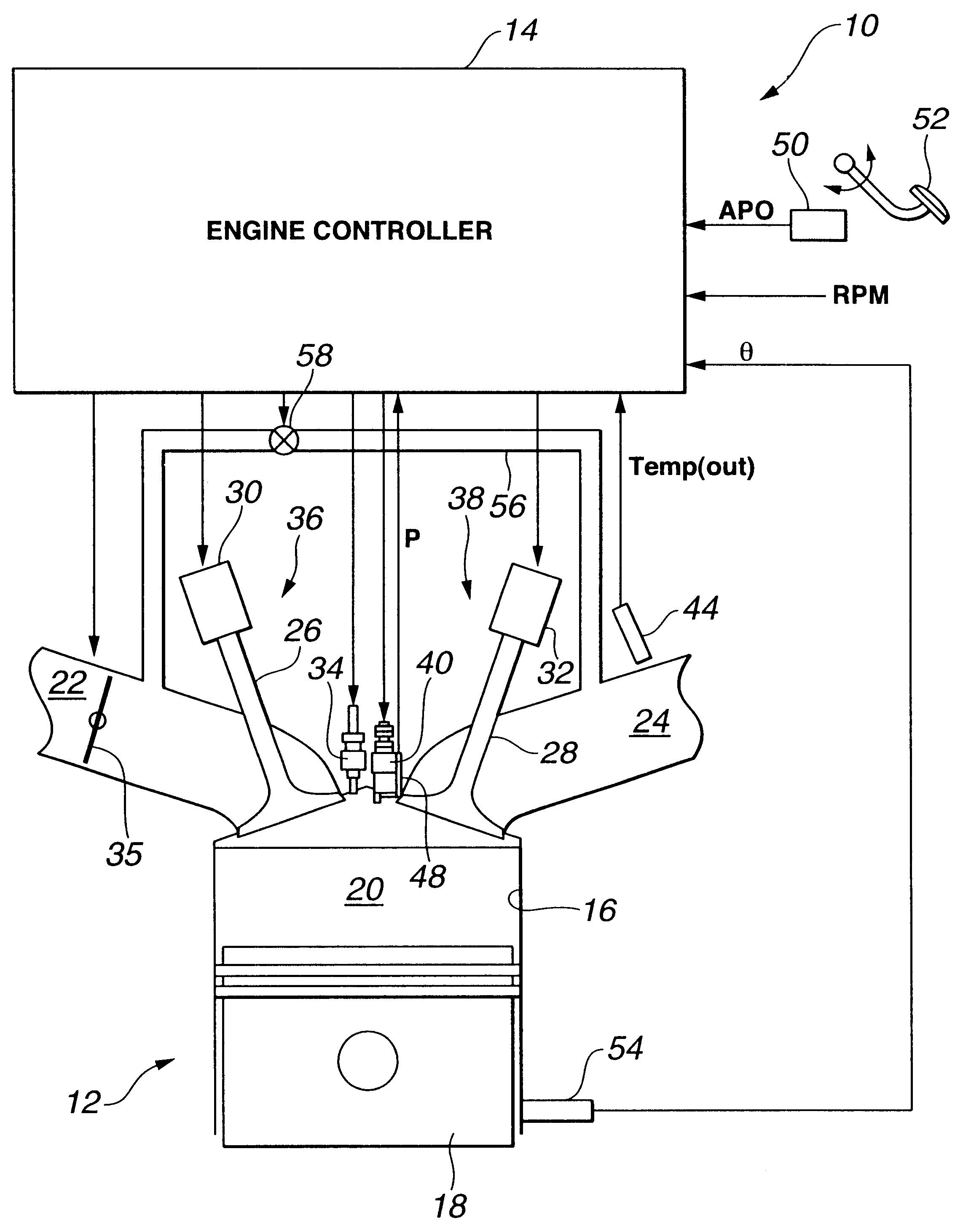
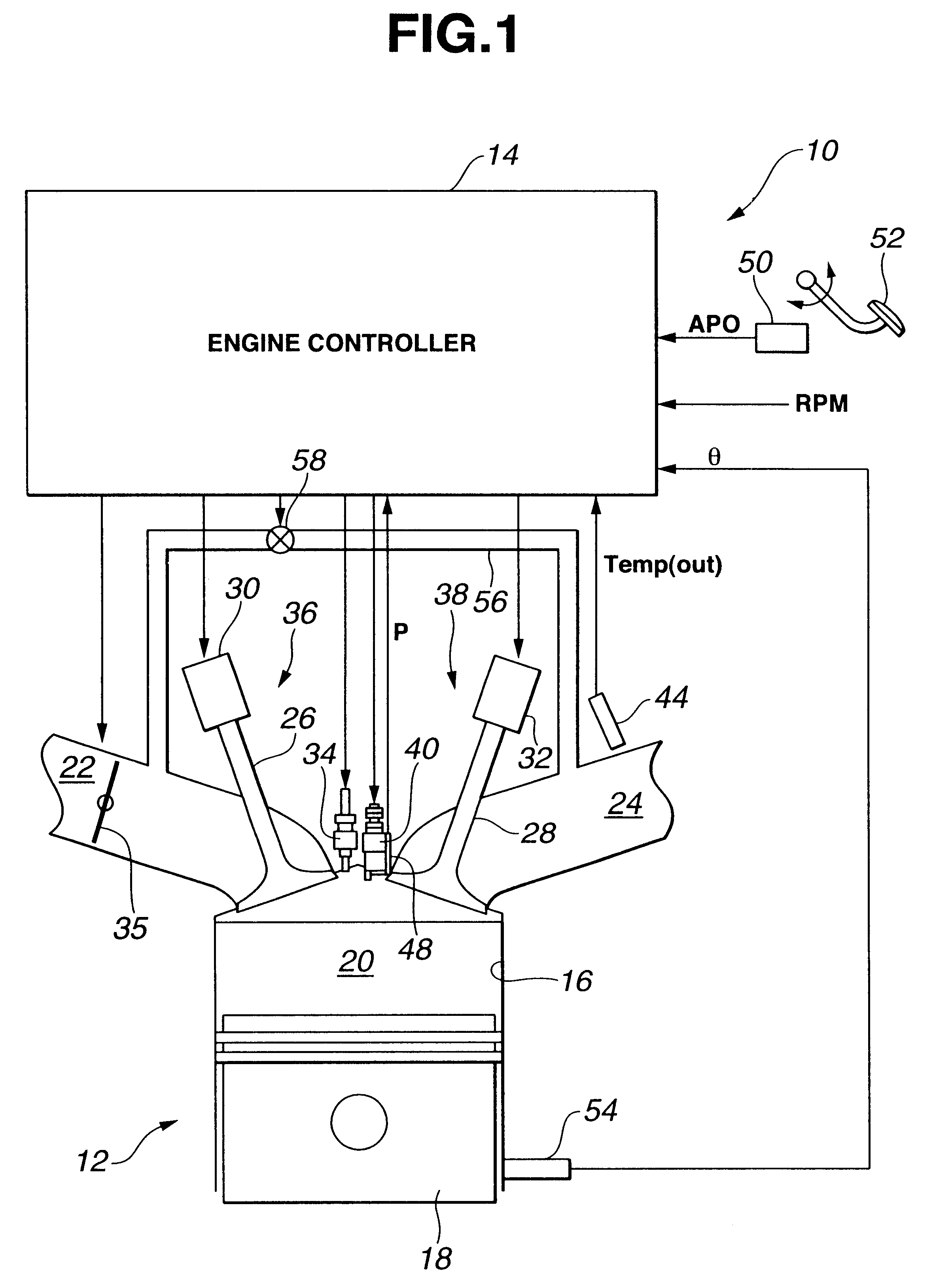
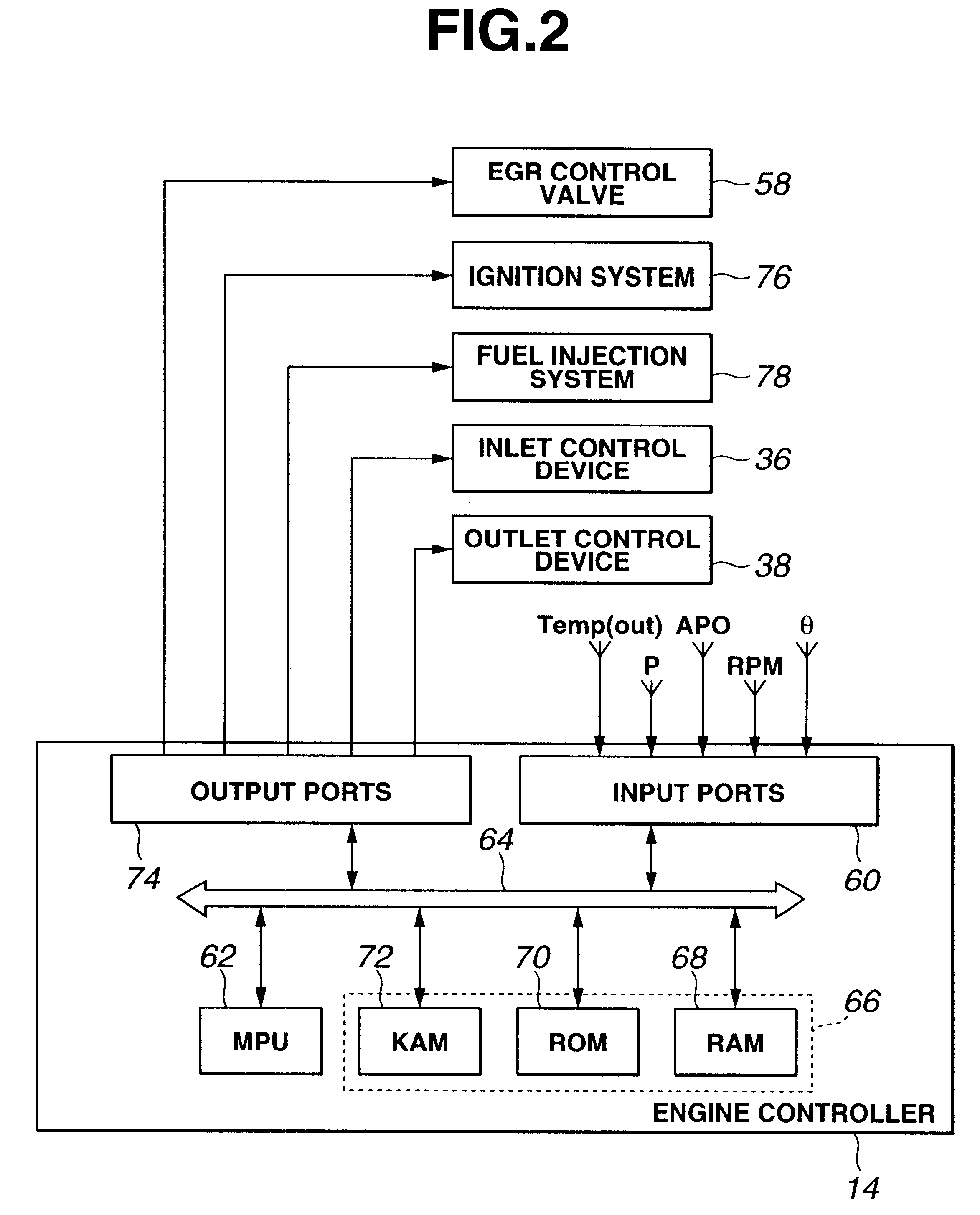
This fourth embodiment requires an exhaust gas temperature sensor 44, an EGR control valve 58 and an EGR conduit 56.

As mentioned before, in the embodiments, auto-ignition combustion is achieved at low and middle load, while spark-ignition combustion is accomplished at high speed with high load. Fuel with low cetane number, such as, gasoline, is difficult to ignite as compared to fuel with high cetane number, such as fuel for diesel engines. To achieve auto-ignition of gasoline fuel, it is useful to elevate temperature of mixture. In the fourth embodiment, exhaust gas from the EGR conduit is utilized to elevate the cylinder temperature.

FIG. 25 provides variation of BOB against variation of total fuel quantity q and cylinder temperature Temp when air / fuel mixture is homogeneous. In FIG. 25, a plurality of lines 290, 292, 294, 296, 298, and 300 are illustrated, each connecting equal crank angle for BOB against variation of fuel quantity q and cylinder temperature Temp. The crank angles...


PUM


Abstract

An internal combustion engine has a fuel injection system capable of performing a multiple injection wherein a main injection event and a trigger injection event take place in this order in one cycle. With main injection, fuel is widely dispersed within a combustion chamber to create a main mixture for main combustion. With trigger injection, fuel is dispersed locally within the combustion chamber to create an ignitable mixture for auto-ignition. Auto-ignition of the ignitable mixture creates condition under which auto-ignition of the main mixture takes place. Fuel quantity and timing for each of main and trigger injections are varied corresponding to engine speed and load request to cause the main mixture to burn at a target crank angle after TDC of compression stroke.

Description

1. Field of the InventionThe present invention relates to an internal combustion engine capable of operating on auto-ignition combustion, and a system for and a method of controlling fuel delivery in a fuel injection system capable of performing a multiple injection wherein a main injection event and a trigger injection event take place in this order in one cycle.2. Description of Related ArtWhen certain conditions are met within a charge of lean air / fuel mixture during low load operation, auto-ignition can occur wherein bulk combustion takes place initiated simultaneously from many ignition sites within the charge, resulting in very stable power output, very clean combustion and high thermal efficiency. NOx emission produced in controlled auto-ignition combustion is extremely low. In controlled auto-ignition combustion where the combustion is uniformly distributed throughout the charge from many ignition sites, the burnt gas temperature is substantially homogeneous with much lower ...

Claims


Application Information

Patent Timeline
Patent Type & Authority Patents(United States)
IPC IPC(8): F02D13/02F02D41/30F02B1/12F02D41/40F02B1/00F02B23/10F02M25/07F01L13/00F01L9/04F02B11/00F02D21/08F02D41/02F02D41/38F02D43/00
CPCF02B1/12F02D13/0215F02D13/0265F02D41/405F02D41/3047F02B23/101F02D41/005Y02T10/44F02D2041/389F02M25/0715Y02T10/18F02M26/13Y02T10/12Y02T10/40
Inventor YOSHIZAWA, KOUDAITERAJI, ATUSHIMIYAKUBO, HIROSHIHIRAYA, KOJI
Owner NISSAN MOTOR CO LTD
Why Eureka
Try Eureka