Non-destructive inspection, testing and evaluation systems for intact aircraft and components and method therefore

a technology of inspection and evaluation system and aircraft, which is applied in the direction of vibration measurement in solids, instruments, processing detected response signals, etc., can solve the problems of inefficiency, cost, and inability to solve the safety problems of "aging aircraft", and the inspection and repair procedures and processes have changed little, so as to minimize the need for highly experienced personnel and facilitate use.

Inactive Publication Date: 2003-10-28
FROOM DOUGLAS ALLEN
View PDF7 Cites 167 Cited by
  • Summary
  • Abstract
  • Description
  • Claims
  • Application Information

AI Technical Summary

Benefits of technology

It is a further object of this invention to provide a method and apparatus as characterized above which accurately forecasts the need for corrective measures in a timely manner.
It is a further object of this invention to provide a method and apparatus which is easy to use and minimize the need for highly experienced personnel.
It is a further object of this invention to provide a method and apparatus where the system and method can be reliably replicated.

Problems solved by technology

Recent tragedies in aircraft transportation have caused concern over the ability of airlines to evaluate the airworthiness of aircraft within their respective fleets.
Current commercial industry inspection and repair methods are inefficient, costly and not standardized.
Their inspection and repair procedures and processes have changed little in the past 20 or 30 years and have not solved the "Aging Aircraft" safety problems.
Inspection of aircraft components are historically limited to the "Tap Test," visual inspection, and Eddy Current analysis.
Commercial safety integrity is continually compromised by not determining the extent of aircraft structure corrosion and fatigue.
Unfortunately, manned inspection is still the state of the art.
This can result in a costly endeavor because the aircraft component is destroyed even though it passed the test procedure.
It is, therefore, no longer available for use.
Frequently, where destructive testing is done on samples (e.g. coupons) and not on actual components, the destructive test may or may not be reflective of the forces that the actual component could or would withstand within the flight envelope of the aircraft.
Still, the accuracy of X-rays is generally no better than +10% void content.
The difficulty is the obvious problem with safety and radiation sources. addition to the normal use to detect internal flaws in the metals and composite structures, X-rays and neutrons can detect misalignment of honeycomb cores afte
Quantitative interpretation is not yet possible except for well-documented and simple shapes (such as cylindrical pressure vessels).
If the internal flaws are small or far removed from the surface, however, they may not be detected.
This method has had limited acceptance because of the need to isolate the camera and sample from vibrations.
However, in this case an image-shearing camera is used in which signals from the two images are superimposed to give interference and thereby reveal the strains in the samples.
When used separately, certain imaging inspection methods find certain aircraft structural defects.
Secondly, multiple robots avoid the need for a single long supporting beam, which would reduce positioning accuracy and repeatability.
Any pendulum or sway effect at the bottom of the mast (with yoke attached) causes the real-time radiography image to be un-focused, distorted and unreadable to the operator.
At issue is the facility's hangar door.
As the robots are moved closer to the hangar door, the pendulum effects become unacceptable.
This wing configuration causes sharp radial surface turns at the fore and aft ends of the wings' leading and trailing edge surfaces and the inability for a normal "C" shaped yoke to conform to these areas to perform a total inspection perpendicular to the part under inspection.

Method used


Image

  • Non-destructive inspection, testing and evaluation systems for intact aircraft and components and method therefore
  • Non-destructive inspection, testing and evaluation systems for intact aircraft and components and method therefore
  • Non-destructive inspection, testing and evaluation systems for intact aircraft and components and method therefore

Examples


Embodiment Construction

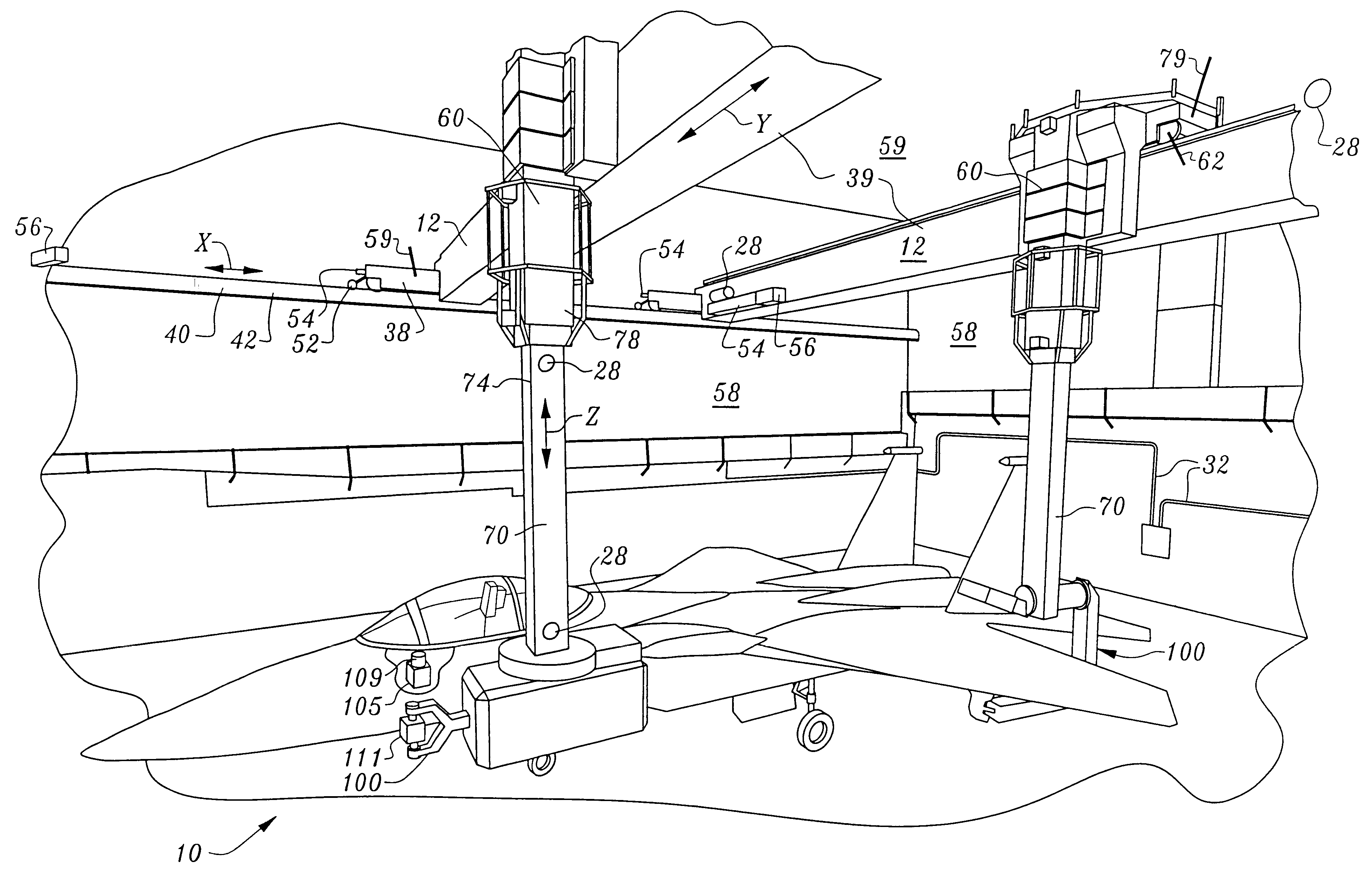
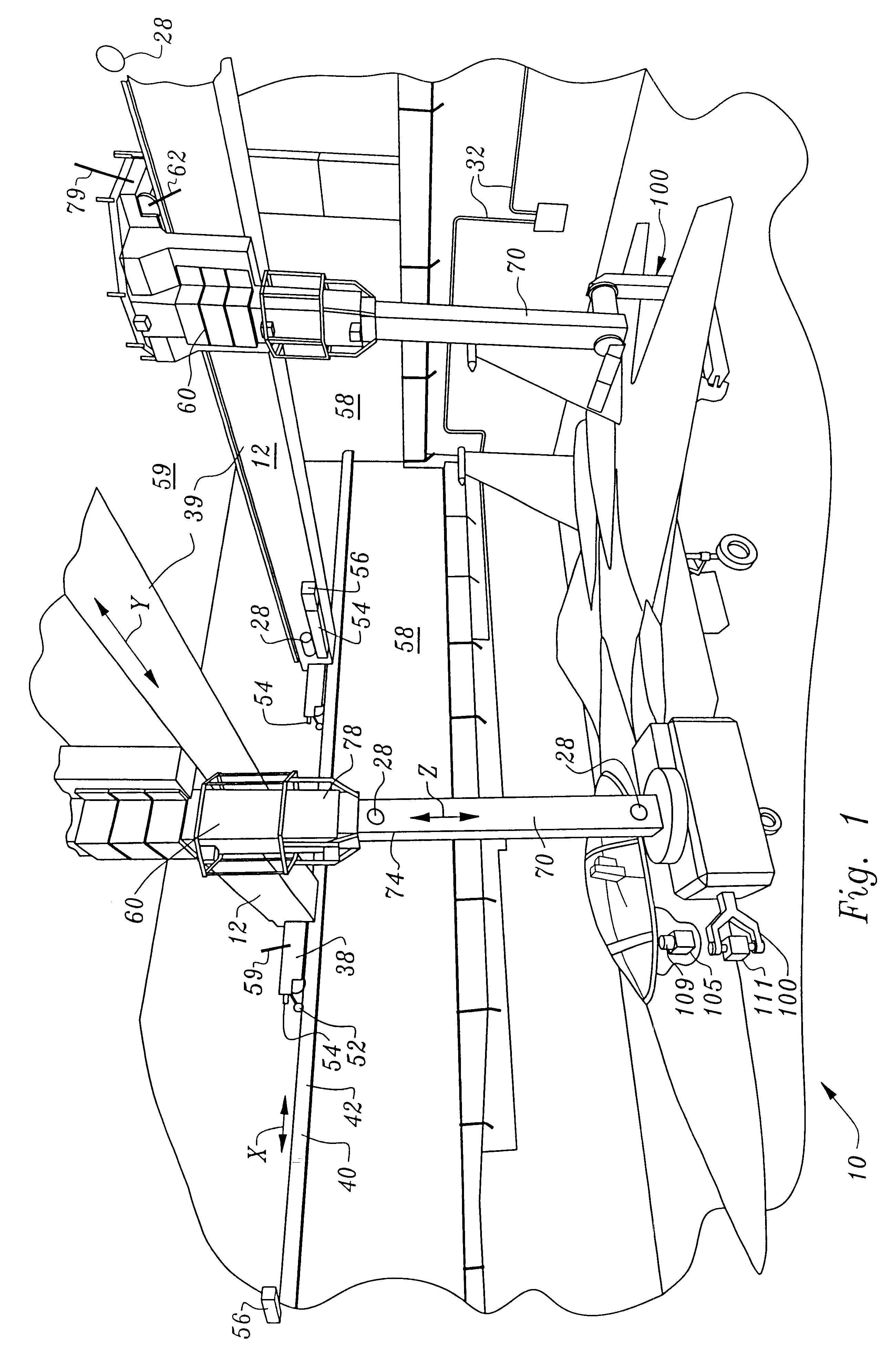
Considering the drawings, wherein like reference numerals denote like parts throughout the various drawing figures, reference numeral 10 is directed to the non-destructive inspection and testing system for aircraft components according to the present invention.

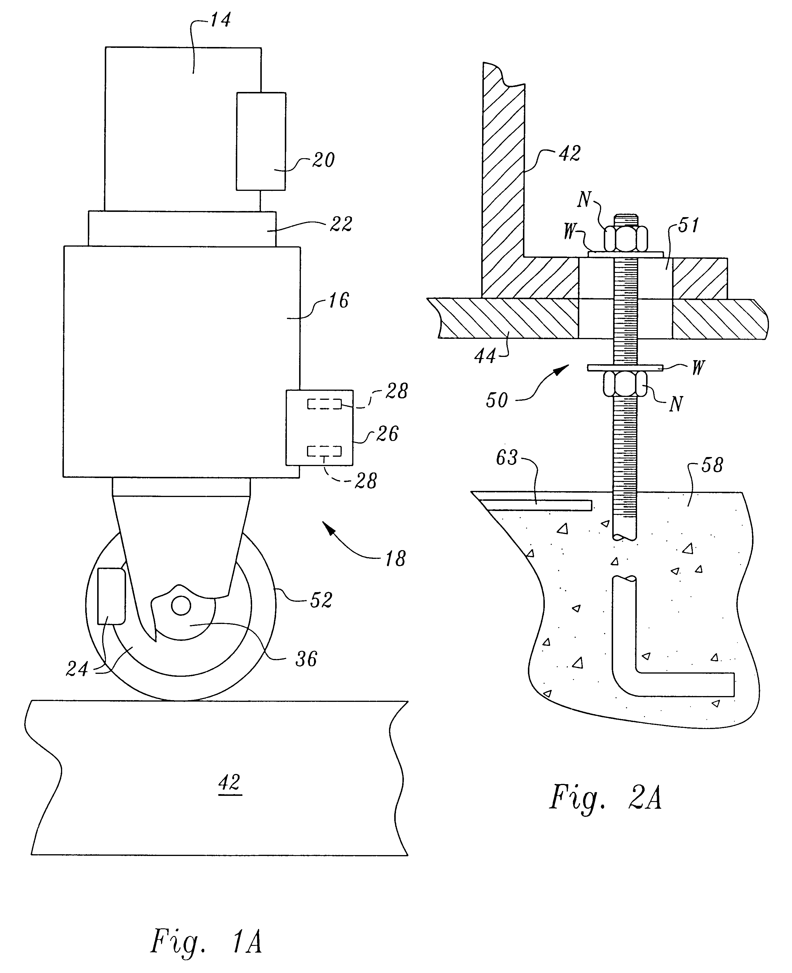
The Robotic Overhead Positioner (ROP), (e.g., FIG. 1) is a gantry robot that resembles an overhead crane. The ROP allows movement in three linear directions (X, Y, and Z) and three rotational directions (Yaw, Pitch and Roll to be described). Generally, to move in each of these directions, it uses a variable-speed DC motor 14 (FIG. 1A), a gearbox 16, and a drive mechanism 18 having wheels 52. Power to turn the motor (thus moving the robot) is supplied by a controller 20. Each motor 14 has an encoder 22, which tells the controller 20 the distance of travel; and it also has a solenoid energized electric disc brake 24, which keeps the robot in a frozen position whenever the controller 20 is not supplying power to the motor 14. For...


PUM

PropertyMeasurementUnit
lengthaaaaaaaaaa
lengthaaaaaaaaaa
depthaaaaaaaaaa

Abstract

A non-destructive inspection, testing and evaluation system and process is provided for the review of aircraft components. The system provides for a structure configured to contain an inspection and testing apparatus and the aircraft components under inspection. The structure is lined with shielding to attenuate the emission of radiation to the outside of the structure and has corbels therein to support the components that constitute the inspection and testing apparatus. The inspection and testing apparatus is coupled to the structure, resulting in the formation of a gantry for supporting a carriage and a mast is mounted on the carriage. The inspection and testing equipment is mounted on the mast which forms, in part, at least one radiographic inspection robot capable of precise positioning over large ranges of motion. The carriage is coupled to the mast for supporting and allowing translation of the equipment mounted on the mast. The mast is configured to provide yaw movement to the equipment.

Description

The following invention is generally related to instrumentalities and methodologies for the non-destructive inspection, and especially for testing and evaluation of aircraft components.Recent tragedies in aircraft transportation have caused concern over the ability of airlines to evaluate the airworthiness of aircraft within their respective fleets. As airframes age, the characteristics of the materials that constitute the airframe components change due to the stresses and strains associated with flights and landings. The material goes beyond the point of elasticity (the point the material returns to its original condition) and into the point of plasticizing or worse, beyond to failure. As a result, inspections and testing are conducted on aircraft components periodically during the aircraft's component life cycle as are mandated by governing bodies and based largely on empirical evidence.Current commercial industry inspection and repair methods are inefficient, costly and not stand...

Claims


Application Information

Patent Timeline
Patent Type & Authority Patents(United States)
IPC IPC(8): G01N29/44G01N29/26G01N29/22G01N29/265G01N29/24
CPCG01M5/0016G01M5/0033G01M5/0075G01M5/0091G01N29/225G01N29/265G01N29/4418G01N29/2418G01N2291/2694G01N2291/0231G01N2291/0234
Inventor FROOM, DOUGLAS ALLEN
Owner FROOM DOUGLAS ALLEN
Why Eureka
Try Eureka