Dual-diaphragm differential pressure flow rate sensor

a flow rate sensor and diaphragm technology, applied in the direction of instruments, liquid/fluent solid measurement, pressure difference measurement between multiple valves, etc., can solve the problems of low sensitivity, frequent correction and zero adjustment, and sensitivity and pressure resistan

Inactive Publication Date: 2003-11-04
ADVANCE DENKI KOUGYOU
View PDF3 Cites 69 Cited by
  • Summary
  • Abstract
  • Description
  • Claims
  • Application Information

AI Technical Summary

Benefits of technology

According to a first aspect of the invention, there is provided a flow rate sensor comprising a chamber with first and second diaphragms arranged therein in opposed relation to each other, wherein the chamber is divided into a primary chamber facing the first diaphragm and a secondary chamber facing the second diaphragm, wherein a fluid is passed from the primary chamber to the secondary chamber through a bypass having an orifice member thereby to generate a differential pressure between the primary chamber and the secondary chamber, wherein the load difference generated by the fluid pressure fluctuations received by the first diaphragm and the second diaphragm is detected as a displacement by a load difference sensor arranged between the first diaphragm and the second diaphragm thereby to detect the flow rate of the fluid, and wherein a selected one of the diaphragm pair and the load difference sensor includes at least a displacement limiting member for preventing the displacement generated by the fluid pressure fluctuations received by the diaphragms from increasing beyond a predetermined amount.

Problems solved by technology

This system, however, poses a great problem in respect to sensitivity and pressure resistance.
Specifically, in the case where the portion of the system downstream of the flow rate sensor is closed, a large pressure is imposed and, therefore, a pressure sensor having a high pressure resistance is required, resulting in a lower sensitivity.
Also, the use of two sensors leads to different drift characteristics (temperature, source voltage, etc.) due to the individual differences of the pressure sensors, which in turn poses the problem that correction and the zero adjustment, after a calculation, are frequently required.
Reducing the thickness of the movable member of the load difference sensor for improving the sensitivity thereof, however, would erroneously exert a high pressure on the primary or secondary side.
Also, in the case where an excessive flow rate exceeds the measurable range, the limit of elasticity of the movable member of the load difference sensor is exceeded, thereby damaging the movable member or making it impossible to restore the zero point.
Increasing the pressure resistance of the movable member of the load difference sensor, on the other hand, would reduce the sensitivity against the differential pressure in respect of the flow rate, with the result that a wide range of the measurement ability of the flowmeter cannot be secured.
Thus, the accuracy would be adversely affected without allowing a large pressure loss in the chamber by reducing the orifice diameter or otherwise.

Method used


Image

  • Dual-diaphragm differential pressure flow rate sensor
  • Dual-diaphragm differential pressure flow rate sensor
  • Dual-diaphragm differential pressure flow rate sensor

Examples


Embodiment Construction

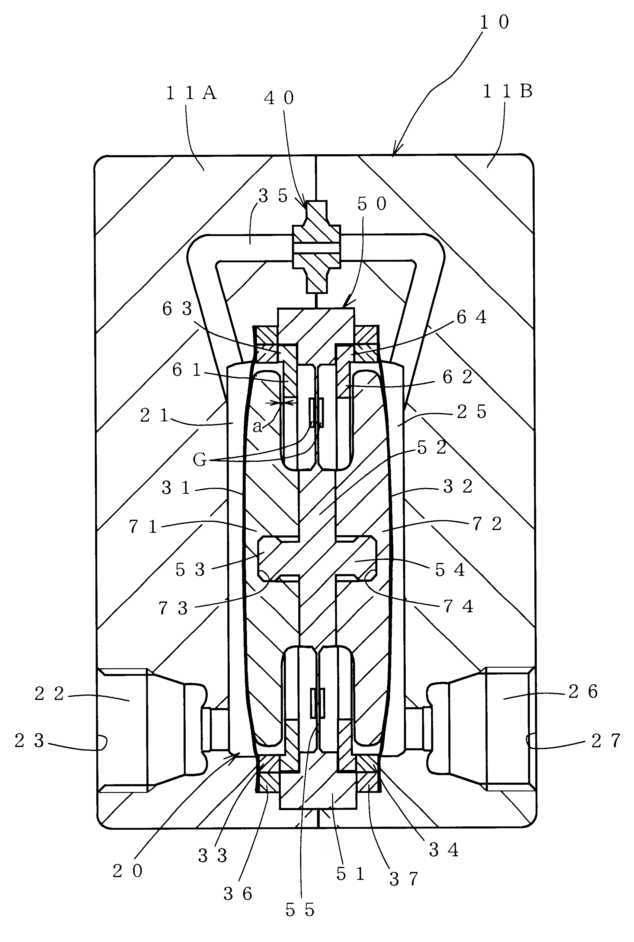
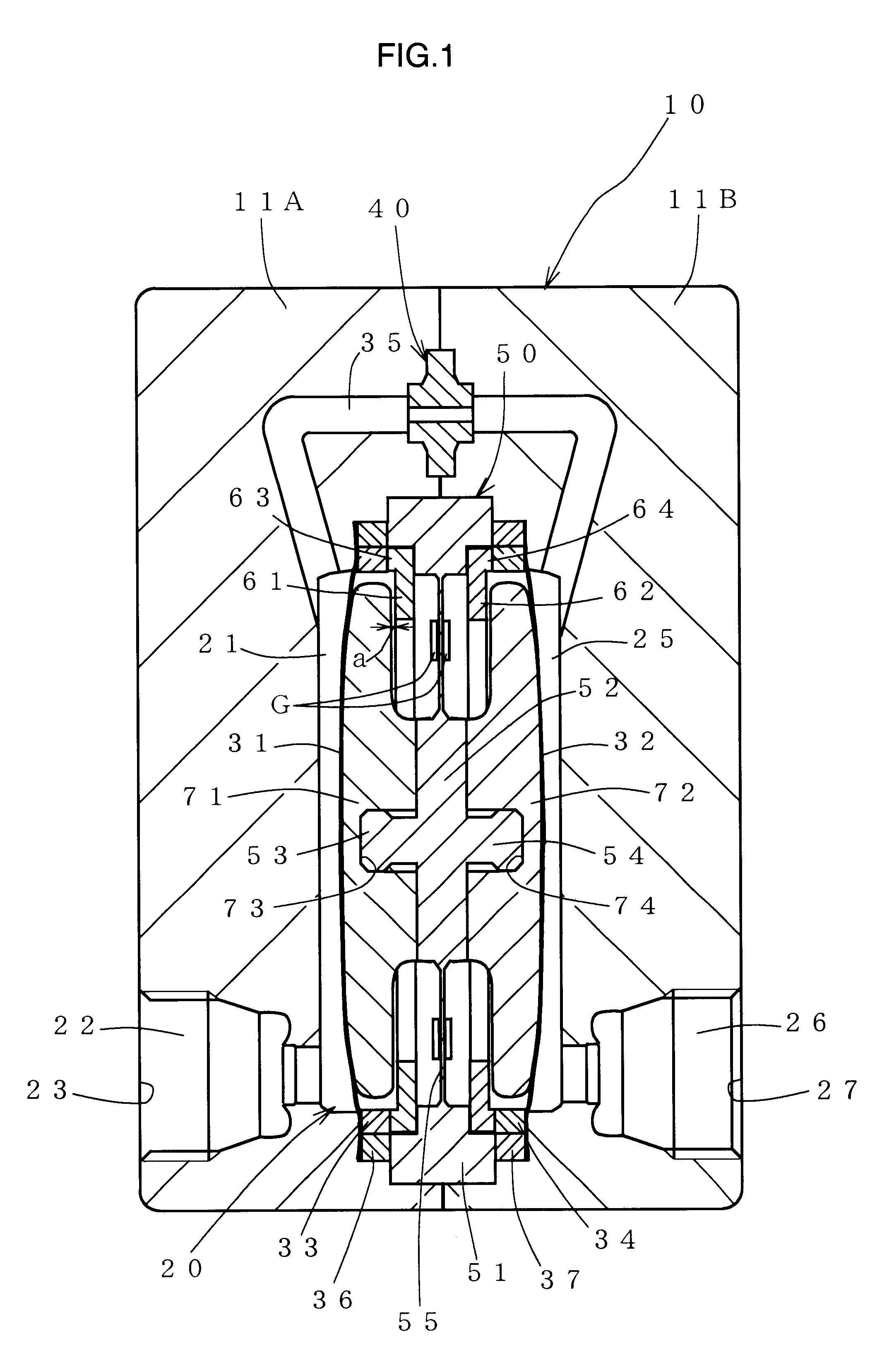
As shown in FIGS. 1 to 3, a flow rate sensor 10 according to the invention is used for measuring a very small flow rate of ultrahigh pure water or chemical liquids as described above. Two diaphragms, i.e. a first diaphragm 31 and a second diaphragm 32 receive the pressure fluctuations of the fluid passing through a chamber 20. The load difference between the first and second diaphragms 31, 32 is detected by a load difference sensor 50 as an amount of displacement thereby to detect the flow rate of the fluid.

Especially, the flow rate sensor 10 according to the invention has the feature in that the diaphragms 31, 32 (FIGS. 1, 2) or the load difference sensor 50 (FIG. 3) include displacement limiting members 61, 62 (FIGS. 1, 2), 66, 67 (FIG. 3), respectively, in order that the displacement generated by the fluid pressure fluctuations received by the first diaphragm 31 and the second diaphragm 32 may not exceed a predetermined amount. The displacement limiting members is not necessarily...


PUM

PropertyMeasurementUnit
displacementaaaaaaaaaa
flow rateaaaaaaaaaa
flow rateaaaaaaaaaa

Abstract

A flow rate sensor high in pressure resistance has a structure to facilitate the measurement of a minuscule differential pressure for measurement of a very small flow rate. A chamber (20) is defined into a primary chamber (21) and a secondary chamber (25) by two diaphragms (31, 32) arranged in an opposed relation to each other. A fluid is passed from the primary chamber to the secondary chamber through a bypass (35) having an orifice portion (40) thereby to generate a differential pressure. The load generated by the fluid pressure fluctuations received by the first and second diaphragms is detected as a difference of displacement by a load difference sensor (50) arranged between the first and second diaphragms thereby to detect the flow rate of the fluid. Displacement limiting members (61, 62) are provided for the diaphragms or the load difference sensor so that the displacement due to the fluid pressure fluctuations received by the first and second diaphragms may not exceed a predetermined amount.

Description

1. Field of the InventionThe present invention relates to a sensor for measuring the flow rate of a fluid or, in particular, to a flow rate sensor employing a diaphragm.2. Description of the Related ArtAs a means for measuring the flow rate of a fluid, a system in which the pressure of each of two pressure sensors arranged with an orifice held therebetween is calculated, is generally known. This system, however, poses a great problem in respect to sensitivity and pressure resistance. Specifically, in the case where the portion of the system downstream of the flow rate sensor is closed, a large pressure is imposed and, therefore, a pressure sensor having a high pressure resistance is required, resulting in a lower sensitivity. Also, the use of two sensors leads to different drift characteristics (temperature, source voltage, etc.) due to the individual differences of the pressure sensors, which in turn poses the problem that correction and the zero adjustment, after a calculation, ar...

Claims


Application Information

Patent Timeline
Patent Type & Authority Patents(United States)
IPC IPC(8): G01F1/38G01F1/34G01F1/42G01L13/02G01L19/06
CPCG01F1/38G01F1/363G01F1/34
Inventor MATSUZAWA, HIRONORISHIBATA, TOMOKO
Owner ADVANCE DENKI KOUGYOU
Why Eureka
Try Eureka