Flap arrangement for varying the aerodynamic lift generated by an aerodynamic element of an aircraft

a technology of aerodynamic elements and flaps, which is applied in the direction of influencers using rotating members, air-flow influencers, transportation and packaging, etc., can solve the problems of not being further developed into a practical useful arrangement, and the general complexity of conventional flap arrangements

Inactive Publication Date: 2003-11-04
AIRBUS OPERATIONS GMBH
View PDF19 Cites 24 Cited by
  • Summary
  • Abstract
  • Description
  • Claims
  • Application Information

AI Technical Summary

Benefits of technology

The shaft or drum may additionally be slidable or shiftable in a direction along the planar trailing edge between the two opposite surfaces of the aerodynamic element. Thereby, the sliding or shifting of the shaft or drum can further accentuate the protrusion height of the auxiliary flap in the first and second positions achieved by rotation of the auxiliary flap about the axis of the shaft or drum.
According to further special features of the invention, a plurality of separately actuatable auxiliary flaps of the above described type can be arranged along the trailing edge of the aerodynamic element. With such an arrangement, the individual auxiliary flaps can be individually and independently actuated so as to either increase, decrease, or not influence the local aerodynamic lift generated by the local associated area or portion of the aerodynamic element, such as a wing. In this manner, the lift distribution and therewith the load distribution along the span of the wing can be easily varied or adjusted.
Further according to the invention, the above described auxiliary flap may be provided on the trailing edge of any conventional lift influencing flap, e.g. along the trailing edge of the landing flap of an aircraft wing. Thereby, the inventive auxiliary flap allows a further adjustment or tailoring of the lift generated by the wing and its main flap, even with the conventional flap selectively extended or retracted into various configurations. The inventive auxiliary flap thus allows a fine-tuning or rapid-tuning adjustment and local variation of the lift generation pattern, of which the overall or gross lift generation is predominantly predetermined by the setting of the main flap.

Problems solved by technology

Such conventionally known flap arrangements are generally rather complicated, i.e. having a complex geometry and construction, and require a complex support and drive mechanism for selectively extending and retracting the flap arrangement.
Although this has been known as a theoretical and experimental concept, it has never been further developed into a practically useful arrangement for varying the aerodynamic lift generated by an aerodynamic element of an aircraft.

Method used


Image

  • Flap arrangement for varying the aerodynamic lift generated by an aerodynamic element of an aircraft
  • Flap arrangement for varying the aerodynamic lift generated by an aerodynamic element of an aircraft
  • Flap arrangement for varying the aerodynamic lift generated by an aerodynamic element of an aircraft

Examples


Embodiment Construction

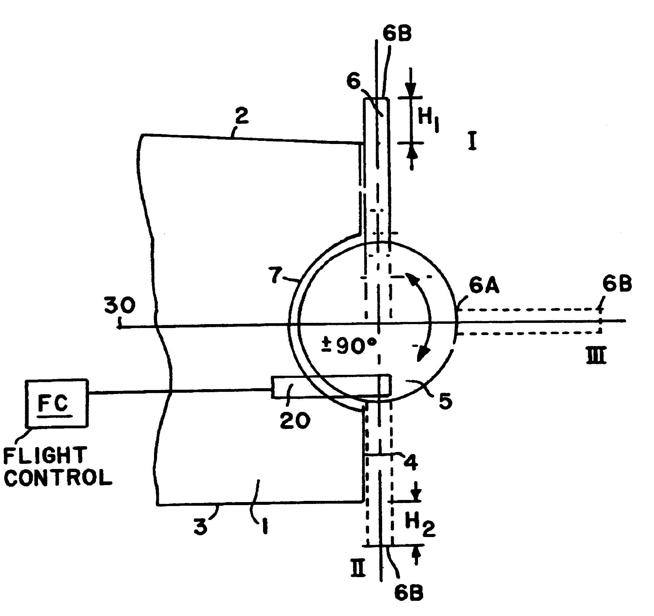
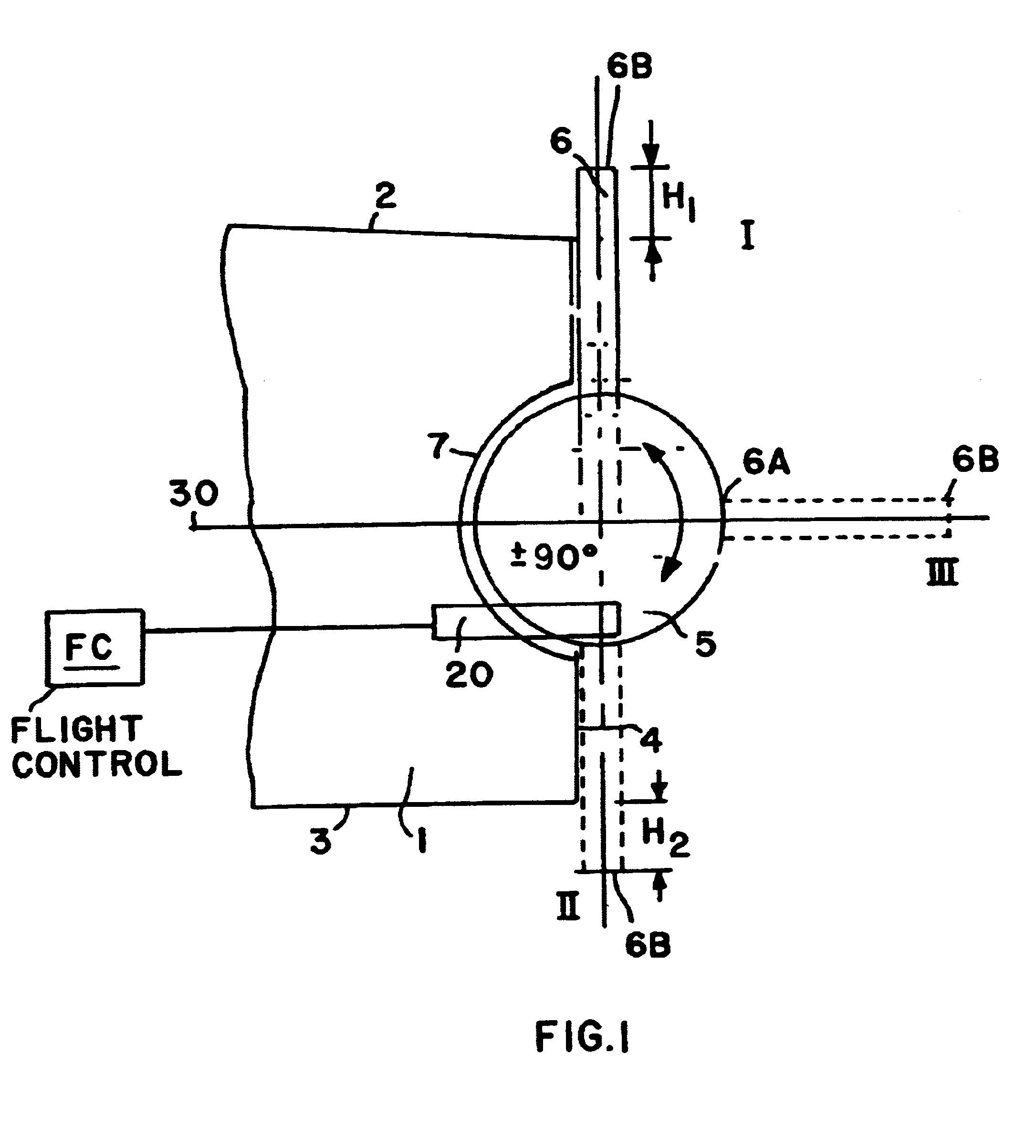
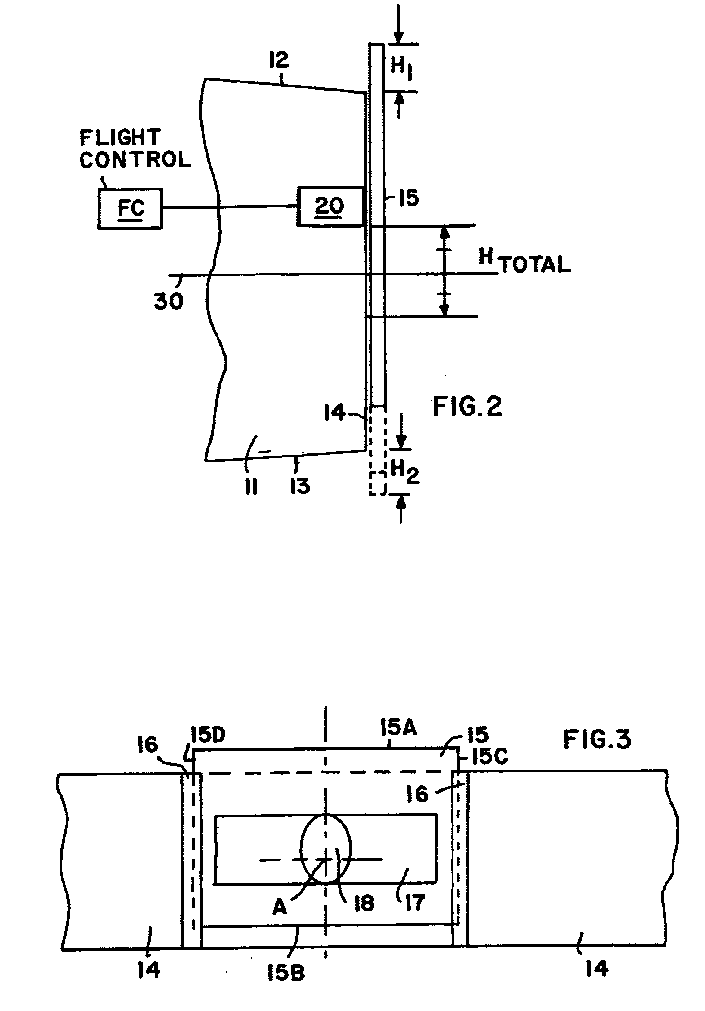
As generally discussed above, the invention relates to the arrangement of an auxiliary flap along the trailing edge of an aerodynamic lift-generating element of an aircraft. The aerodynamic element may be any major aerodynamic element of an aircraft, such as a wing, a main wing flap, an aileron, a rudder, an elevator, a tail plane, a vertical fin, or the like. The drawings show various embodiments of the inventive flap arrangement, in connection with a wing of an aircraft representing an example of the aerodynamic element. In each embodiment of the invention, the auxiliary flap is selectively movable to a first or upper end position in which the auxiliary flap protrudes into the first or upper boundary layer of the airflow along the first or upper surface of the aerodynamic element so as to reduce the aerodynamic lift, or to a second or lower end position in which the auxiliary flap protrudes into the second or lower boundary layer of the airflow along the second or lower surface of...


PUM


Abstract

An auxiliary flap is movably arranged on a planar trailing edge of an aerodynamic element such as a wing, rudder, stabilizer, or flap. The auxiliary flap is rotatable and / or slidable relative to the aerodynamic element, to move selectively into three positions. In a first position, a free edge of the auxiliary flap protrudes into an airflow boundary layer on one side of the aerodynamic element, to decrease lift. In a second position, a free edge of the aerodynamic element protrudes into an airflow boundary layer on the other side of the aerodynamic element, to increase lift. In a third neutral position, the auxiliary element does not protrude into either boundary layer, so as not to influence lift. The auxiliary flap is simple and rapidly acting. The flap protrudes substantially perpendicularly into the boundary layer flow. The auxiliary flap has a planar plate shape.

Description

PRIORITY CLAIMThis application is based on and claims the priority under 35 U.S.C. .sctn.119 of German Patent Application 101 47 827.5, filed on Sep. 27, 2001, the entire disclosure of which is incorporated herein by reference.The invention relates to a flap arrangement that can be selectively extended to protrude into an airflow boundary layer of an aerodynamic element, such as a wing, an aileron, a rudder, an elevator, a stabilizer surface, or a flap, preferably having a planar trailing edge, so as to selectively vary the aerodynamic lift generated by this aerodynamic element.BACKGROUND INFORMATIONA great variety of different flap arrangements for varying the aerodynamic lift generated by an aerodynamic element of an aircraft are generally known. For example, there are many known configurations of high lift flaps arranged along the trailing edge of a main lifting wing of an aircraft. Such conventionally known flap arrangements are generally rather complicated, i.e. having a comple...

Claims


Application Information

Patent Timeline
Patent Type & Authority Patents(United States)
IPC IPC(8): B64C9/00B64C9/18
CPCB64C9/18
Inventor SCHWETZLER, DETLEVMAY, PETER
Owner AIRBUS OPERATIONS GMBH
Why Eureka
Try Eureka