Portable telephone compensable for change of antenna impedance
a technology of antenna impedance change and portable telephone, which is applied in the field of portable telephone, can solve the problems of increased fabrication cost, complicated circuit configuration, and inability to apply the configuration to portable telephones
- Summary
- Abstract
- Description
- Claims
- Application Information
AI Technical Summary
Benefits of technology
Problems solved by technology
Method used
Image

Examples
first embodiment
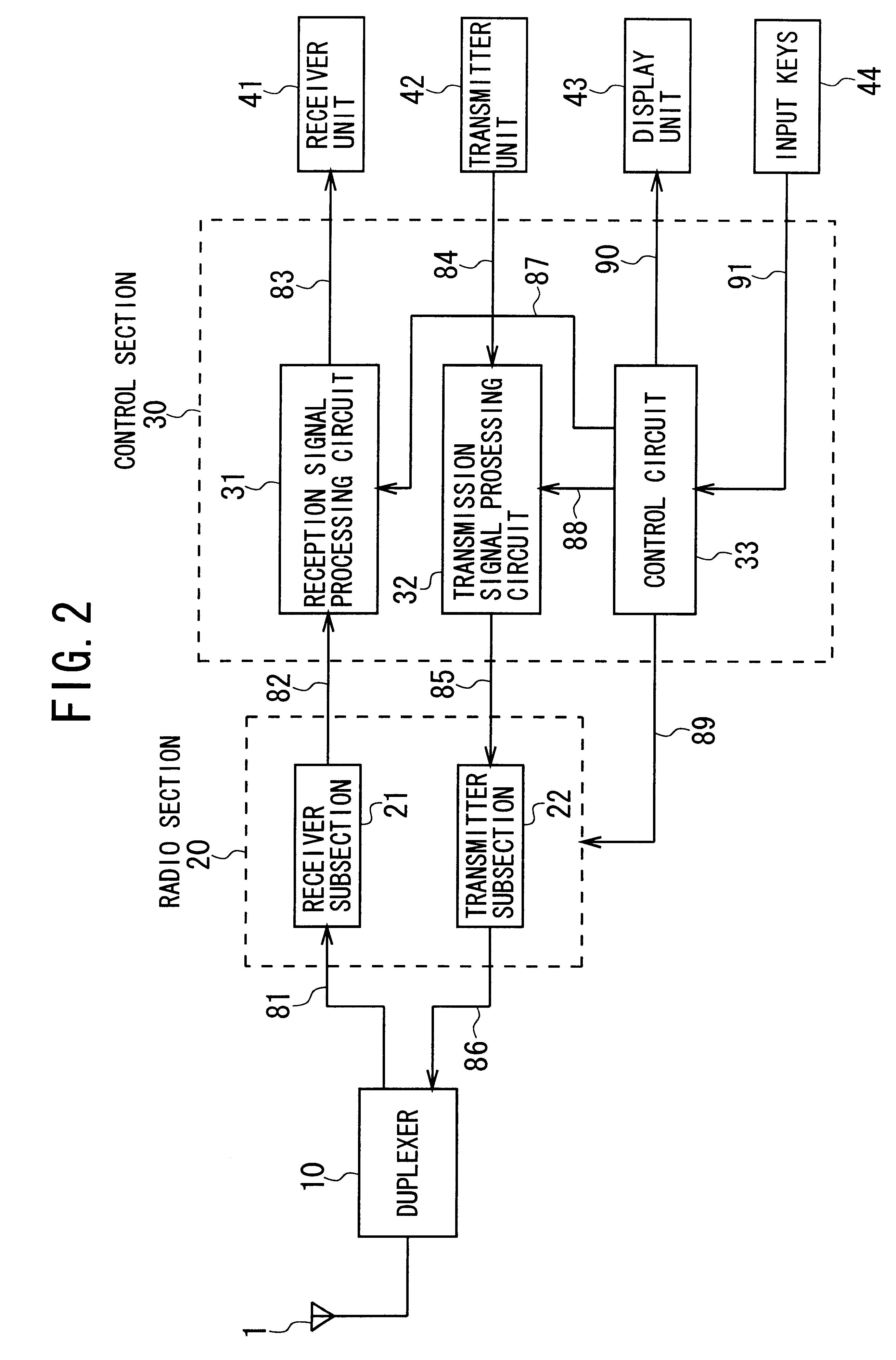
The whole configuration of a portable telephone according to the present invention is shown in FIG. 2. This configuration itself resembles to that of well-known popular portable telephones.
In FIG. 2, an antenna duplexer 10 is provided to enable the common use of an antenna 1 in the transmission and reception operations. The duplexer 10 usually includes an impedance matching circuit (not shown) for matching the impedance between the antenna 1 and a radio section 20, and a filter or filters (not shown) that enable(s) the common use of the antenna 1 in the transmission and reception operations.
The radio section 20 comprises a receiver subsection 21 and a transmitter subsection 22. The receiver subsection 21 receives a Radio-Frequency (RF) reception signal 81 which has been received by the antenna 1 and outputted from the duplexer 10. Then, the receiver subsection 21 amplifies and demodulates the RF reception signal 81 to generate a baseband signal 82. The subsection 21 outputs the sign...
second embodiment
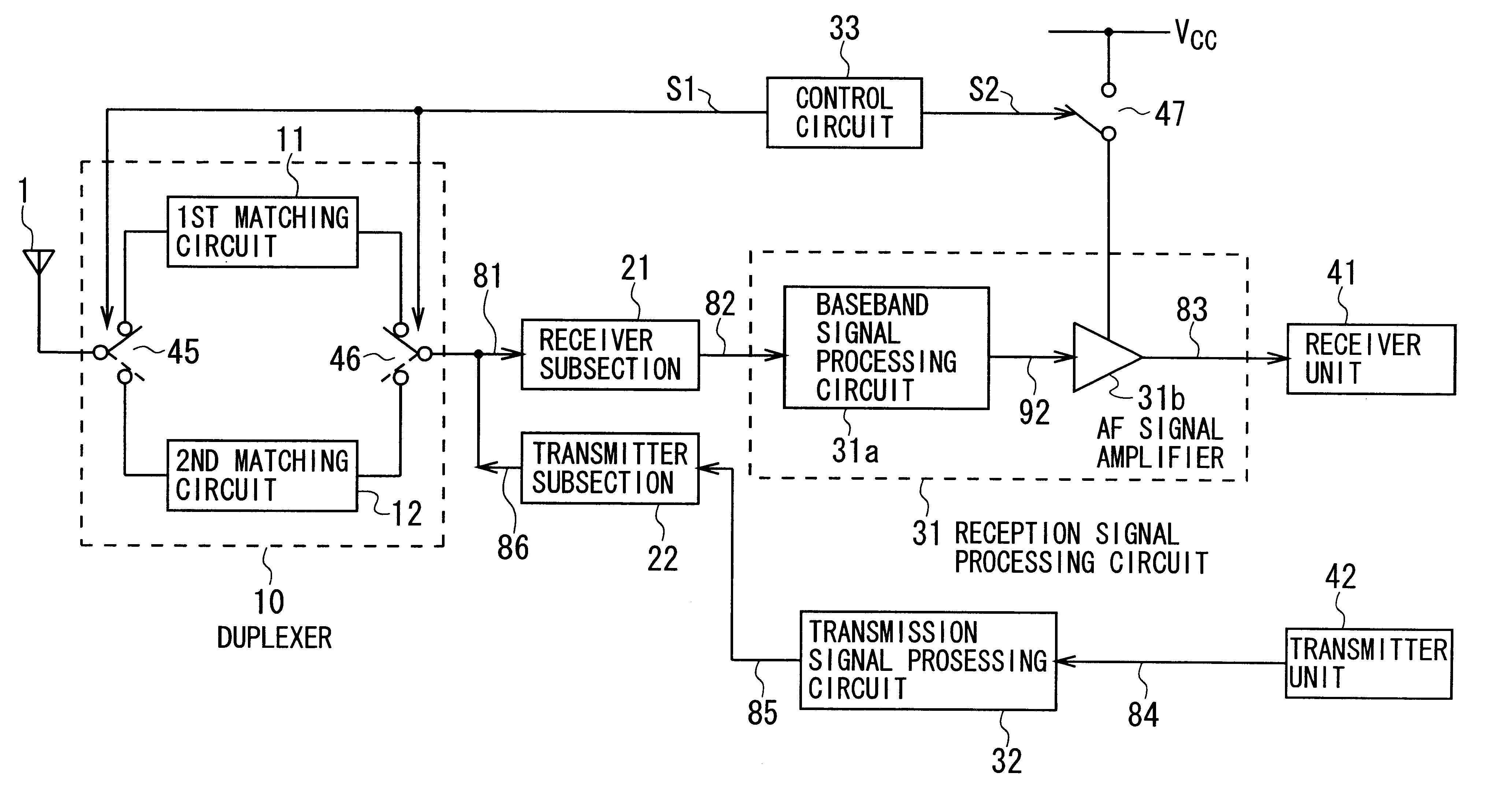
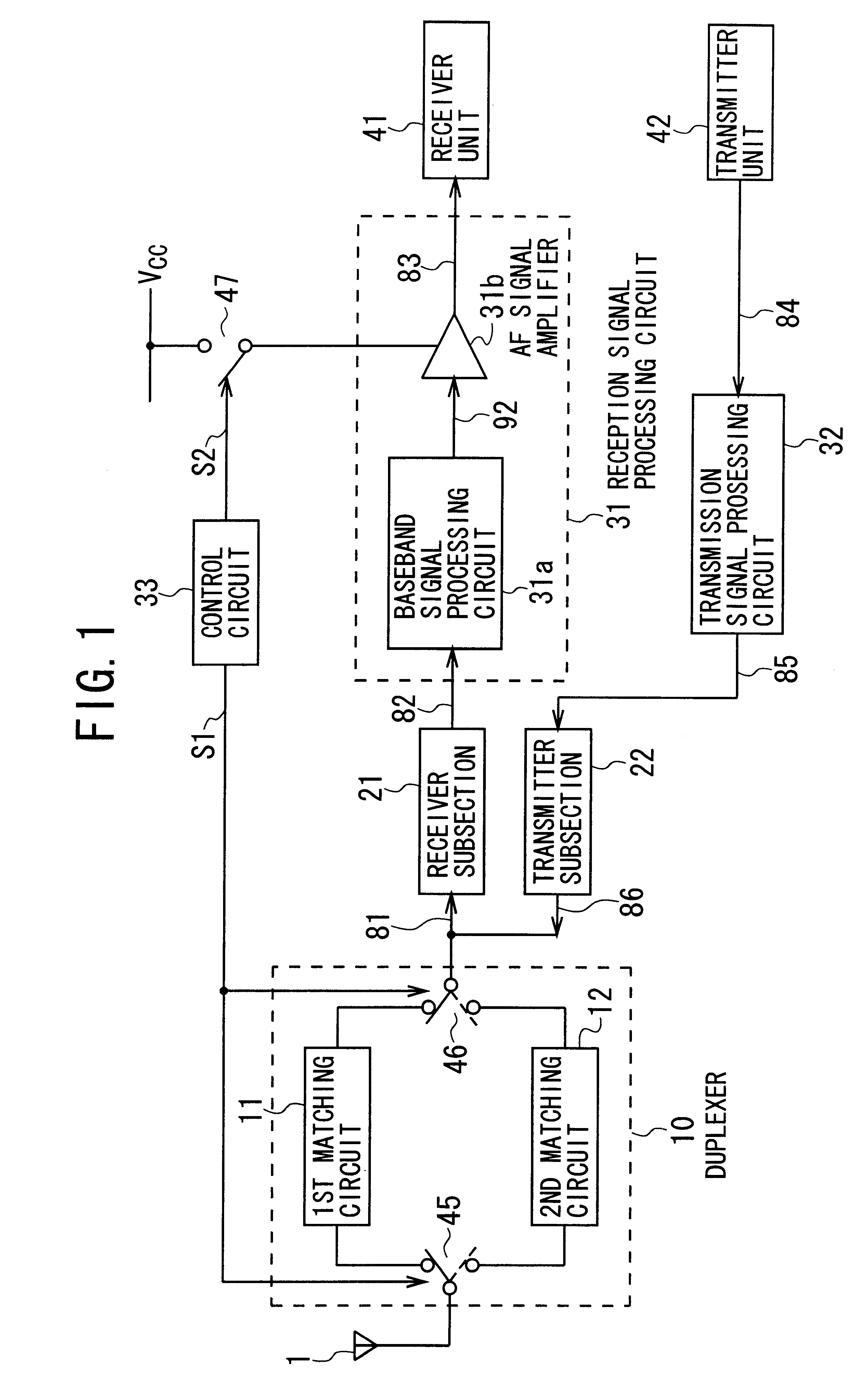
FIG. 8 shows the detailed configuration of a portable telephone according to a second embodiment of the present invention, which is similar to FIG. 1.
The portable telephone according to the second embodiment shown in FIG. 8 has the same configuration as the portable telephone according to the first embodiment of FIG. 1, except that an antenna 1A, third and fourth impedance matching circuits 11A and 12A, and two switches 45A and 46A are additionally provided to enable the diversity reception. Therefore, the explanation about the same configuration is omitted here for the sake of simplification by attaching the same reference symbols as used in the first embodiment to the same elements in FIG. 8.
As shown in FIG. 8, an antenna duplexer 10A, which is provided instead of the antenna duplexer 10 used in the first embodiment, comprises the third and fourth impedance matching circuits 11A and 12A and the switches 45A and 46A for switching the circuits 45A and 46A, in addition to the first a...
third embodiment
FIG. 9 shows the detailed configuration of a portable telephone according to a third embodiment of the present invention, which is similar to FIG. 1.
The portable telephone according to the third embodiment shown in FIG. 9 has the same configuration as the portable telephone according to the first embodiment shown of FIG. 1, except that only the impedance matching circuit 13 shown in FIG. 3 is provided instead of the combination of the first and second impedance matching circuits 11 and 12. Therefore, the explanation about the same configuration is omitted here for the sake of simplification by attaching the same reference symbols as used in the first embodiment to the same elements in FIG. 9.
As explained previously with reference to FIG. 3, the impedance matching circuit 13 has two different impedance values from each other corresponding to the respective impedance values of the first and second impedance matching circuits 11 and 12, in which the two impedance values can be switched...
PUM
 Abstract
Description
Claims
Application Information
 - R&D
- Intellectual Property
- Life Sciences
- Materials
- Tech Scout
- Unparalleled Data Quality
- Higher Quality Content
- 60% Fewer Hallucinations
Browse by: Latest US Patents, China's latest patents, Technical Efficacy Thesaurus, Application Domain, Technology Topic, Popular Technical Reports.
© 2025 PatSnap. All rights reserved.Legal|Privacy policy|Modern Slavery Act Transparency Statement|Sitemap|About US| Contact US: help@patsnap.com