Mobile communication system
a communication system and mobile technology, applied in the field of mobile communication systems, can solve the problems of increasing the cost and complicated circuit of the system, and achieve the effect of simple and low-cost configuration
- Summary
- Abstract
- Description
- Claims
- Application Information
AI Technical Summary
Benefits of technology
Problems solved by technology
Method used
Image
Examples
embodiment 1
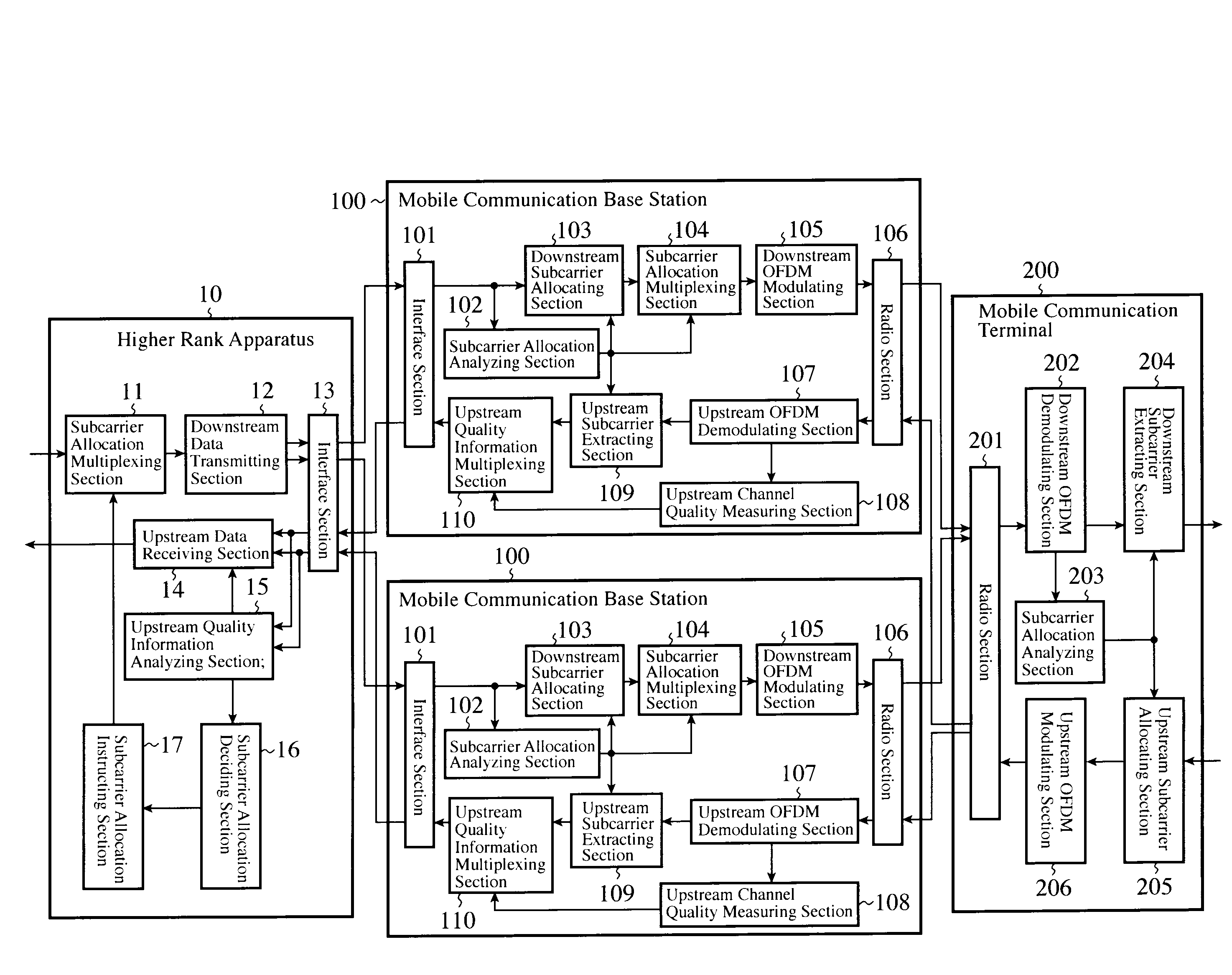
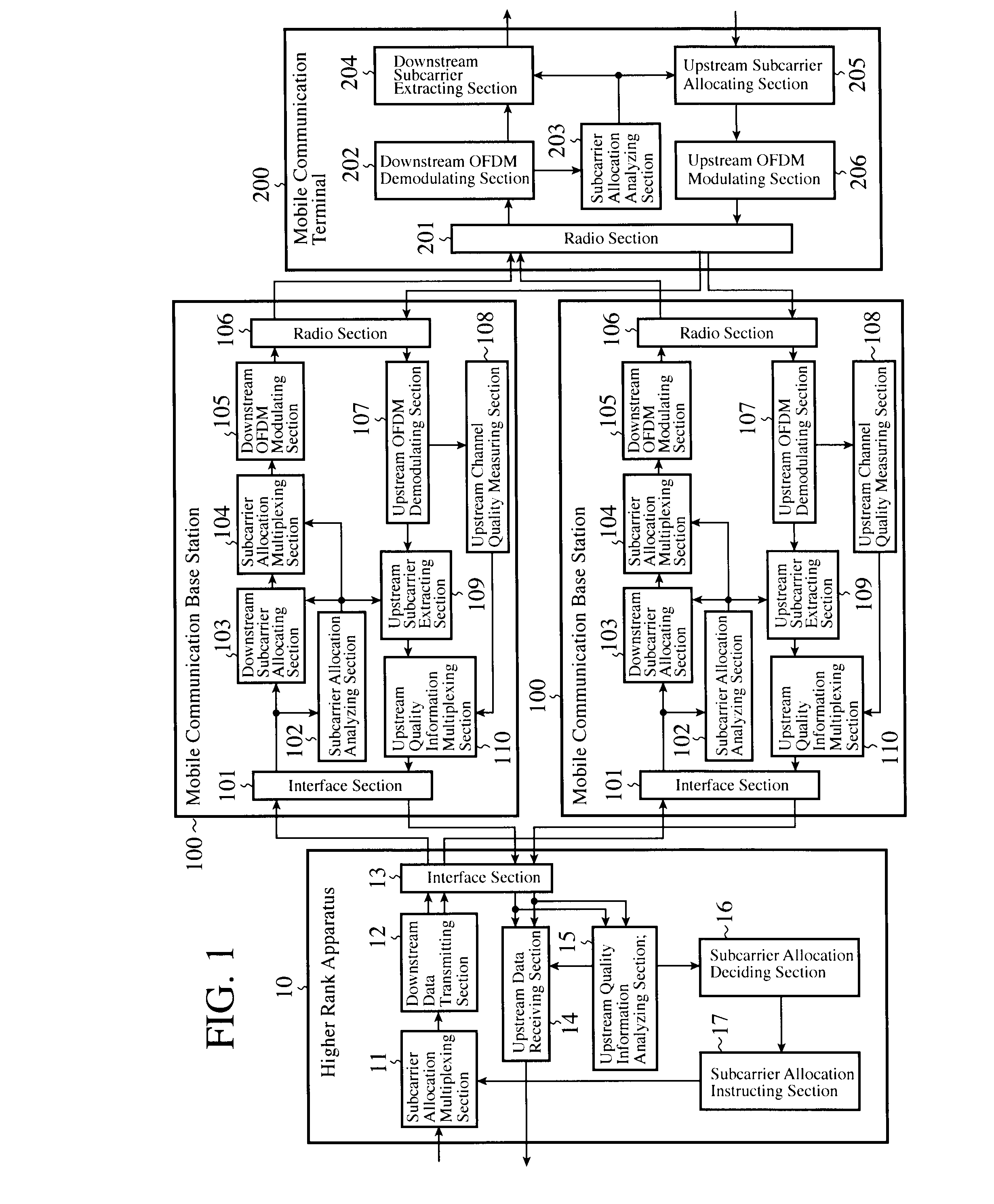
[0016]FIG. 1 is a block diagram showing a configuration of the mobile communication system of the embodiment 1 in accordance with the present invention. The present embodiment 1 relates to a multi-carrier radio communication system between a plurality of mobile communication base stations (BTS) 100 and a mobile communication terminal (MS) 200 based on a TDD (Time Division Duplex) scheme, and shows as an example an OFDM communication system between the two mobile communication base stations 100 and the mobile communication terminal 200.
[0017]The mobile communication system includes a higher rank apparatus 10, a plurality of mobile communication base stations 100 and a mobile communication terminal 200. The higher rank apparatus 10 integrates the plurality of mobile communication base stations 100 to carry out simultaneous communication through a cable network. Each mobile communication base station 100 communicates with the higher rank apparatus 10, and at the same time communicates ...
example 1
[0059]The upstream channel quality measuring section 108 of the mobile communication base station 100 measures the average value of reception levels of all the subcarriers and the reception level of each subcarrier as the upstream channel quality information. The subcarrier allocation deciding section 16 of the higher rank apparatus 10 assigns each mobile communication base station 100 a subcarrier whose reception level is equal to or lower than the average value of reception levels of all the subcarriers in such a manner that the subcarriers do not overlap between the mobile communication base stations 100.
[0060]Here, the reason for assigning the subcarriers whose reception levels are equal to or lower than the average value of reception levels of all the subcarriers is that it is highly probable that these subcarriers are vacant subcarriers which are not used in other communications such as in other mobile communication base stations 100 and in a mobile communication system integr...
example 2
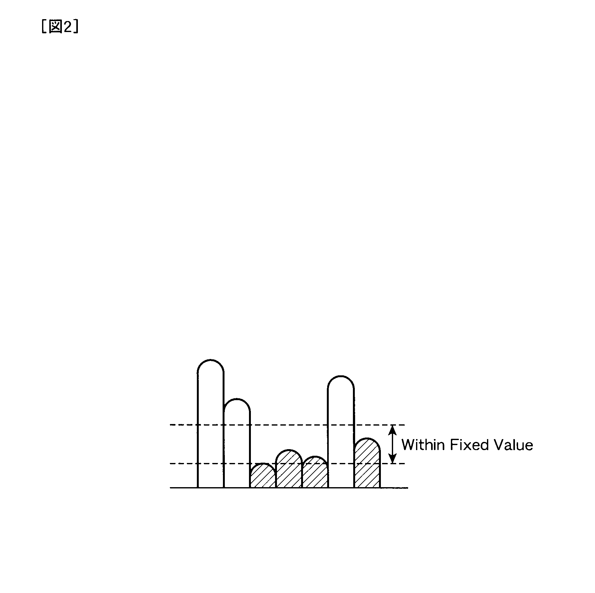
[0061]The upstream channel quality measuring section 108 of the mobile communication base station 100 measures the minimum reception level of all the subcarriers and the reception level of each subcarrier as the upstream channel quality information. The subcarrier allocation deciding section 16 of the higher rank apparatus 10 assigns each mobile communication base station 100 a subcarrier whose reception level is within a fixed range from the minimum reception level in such a manner that the subcarriers do not overlap between the mobile communication base stations 100. Here, the reason for assigning the subcarriers within the fixed range from the minimum reception level is that it is highly probable that they can be vacant subcarriers not used by other communications.
[0062]FIG. 2 is a diagram showing reception levels of the subcarriers. When there are many subcarriers in use, it is likely in the foregoing example 1 that the average value becomes large and that a subcarrier with much...
PUM
 Abstract
Description
Claims
Application Information
 - R&D
- Intellectual Property
- Life Sciences
- Materials
- Tech Scout
- Unparalleled Data Quality
- Higher Quality Content
- 60% Fewer Hallucinations
Browse by: Latest US Patents, China's latest patents, Technical Efficacy Thesaurus, Application Domain, Technology Topic, Popular Technical Reports.
© 2025 PatSnap. All rights reserved.Legal|Privacy policy|Modern Slavery Act Transparency Statement|Sitemap|About US| Contact US: help@patsnap.com


