Image forming apparatus

a technology of forming apparatus and forming sheet, which is applied in the direction of electrographic process apparatus, thin material processing, instruments, etc., can solve the problems of insufficient stiffening amount, low stiffness of sheet, and high probability of roller marks, and achieves simple configuration

Active Publication Date: 2010-11-04
CANON KK
View PDF14 Cites 5 Cited by
  • Summary
  • Abstract
  • Description
  • Claims
  • Application Information

AI Technical Summary

Benefits of technology

[0011]Therefore, it is an object of the present invention to provide an image forming apparatus which has a low-cost and simple configuration, and performs proper stiffening on sheets irrespective of kinds of the sheets.

Problems solved by technology

When the center distance is set to the certain distance, the sheet with low stiffness is short of a stiffening amount, and hence the sheet hangs down because the sheet does not have desired stiffness.
When the sheet has low stiffness, the stiffening amount is insufficient.
When the sheet has high stiffness, the sheet tends to strongly come into contact with the sheet discharge roller pair, and thus the roller marks are likely to occur.
Therefore, it has been a challenge to achieve a balance between a configuration in which stiffening is strongly performed when a sheet with low stiffness such as a thin sheet of paper is fed, and a configuration in which occurrence of the roller marks is reduced through weakly performing stiffening when a sheet with high stiffness such as a thick sheet of paper is fed.
However, according to each of the configurations, it costs to provide a mechanism for transmitting rotation of the motor, and a control circuit for controlling the motor.
Further, the configuration is complicated, and hence there arises a problem in that large space is required and a size of the apparatus is increased.

Method used


Image

  • Image forming apparatus
  • Image forming apparatus
  • Image forming apparatus

Examples


Embodiment Construction

[0024]Hereinafter, with reference to the drawings, an embodiment in which an electrophotographic color laser printer is applied as an example of an image forming apparatus according to the present invention is specifically described. Unless otherwise specified, scope of the present invention should not be construed restrictively in terms of dimensions, materials, and shapes of components, and relative arrangement thereof, which are described in this embodiment.

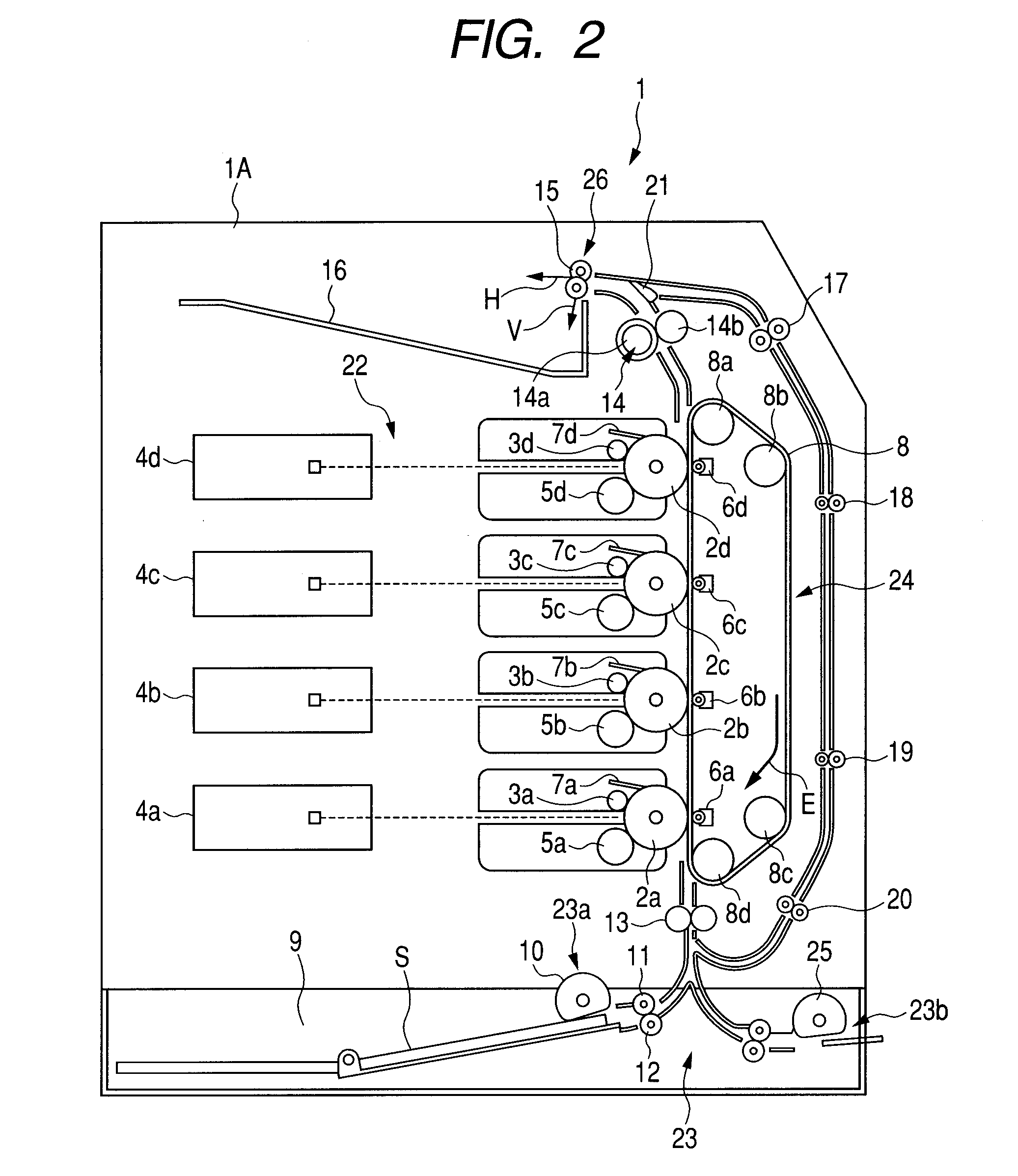
[0025]As illustrated in FIG. 2, a color laser printer main body 1A (hereinafter, referred to as printer main body) of a color laser printer 1 serving as the image forming apparatus includes an image forming unit 22 for forming an image on a sheet, a sheet feeding unit 23, a transfer unit 24, and a fixing device 14. The image forming unit 22 includes photosensitive drums 2 (2a, 2b, 2c, and 2d) serving as image bearing bodies which are arranged in an up-down direction and respectively bear toner images of four colors, i.e., yell...


PUM

PropertyMeasurementUnit
forceaaaaaaaaaa
forceaaaaaaaaaa
diameteraaaaaaaaaa

Abstract

Provided is an image forming apparatus including: a support portion configured to support first and second rollers to be able to increase/decrease a distance between an axis line of the first roller and an axis line of the second roller including a second roller body; an elastic member configured to urge at least one of the first and second rollers to relatively bring it close to the other; and a regulating portion configured to regulate, at a position at which part of the plurality of first roller bodies and part of the second roller body overlap each other in a direction orthogonal to the axial direction, movement of the at least one of the first and second rollers in a direction of increasing the distance between the axis line of the first roller and the axis line of the second roller.

Description

BACKGROUND OF THE INVENTION[0001]1. Field of the Invention[0002]The present invention relates to an image forming apparatus for forming an image on a sheet.[0003]2. Description of the Related Art[0004]In an electrophotographic image forming apparatus such as a printer, a copying machine, or a facsimile, a toner image formed by an image forming unit is transferred onto a sheet, and the sheet with the transferred toner image is discharged to a sheet discharge tray through a sheet discharge roller after the toner image is fixed on the sheet in a fixing unit. There is known a method in which a conveying roller pair for conveying the sheet guides the sheet in between the conveying roller pair including two rollers arranged to be opposed to each other, and the sheet is conveyed while being sandwiched with a frictional force generated between the two rollers. In order to prevent deterioration of performance in stacking sheets on the sheet discharge tray due to a curl of the sheet and insuf...

Claims


Application Information

Patent Timeline
Patent Type & Authority Applications(United States)
IPC IPC(8): G03G15/00B65H29/22
CPCB65H29/22B65H29/70B65H2301/51214B65H2403/40G03G15/6552B65H2404/1451B65H2404/174B65H2801/06B65H2404/144
Inventor SUZUKI, MASATO
Owner CANON KK
Why Eureka
Try Eureka