Pitch driving unit for for wind-turbine rotor blade and wind power generator equipped with the same

a technology of rotor blade and driving unit, which is applied in the direction of rotors, marine propulsion, vessel construction, etc., can solve the problems of contaminating the interior of the rotor head, high manufacturing cost of the wind power generator, and long maintenance time, so as to reduce the amount of oil consumed, reduce the cost, and simple and low-cost configuration

Inactive Publication Date: 2012-05-31
MITSUBISHI HEAVY IND LTD
View PDF4 Cites 5 Cited by
  • Summary
  • Abstract
  • Description
  • Claims
  • Application Information

AI Technical Summary

Benefits of technology

[0014]The present invention has been made to solve the above problems, and an object thereof is to provide a pitch driving unit for a wind-turbine rotor blade in which the intake of air by the hydraulic pump, contamination due to oil, and degradation of the oil and intrusion of foreign substances are prevented, and in which the amount of oil consumed is reduced with a simple and low-cost configuration, which can thus contribute to cost reduction and environmental preservation, as well as a wind power generator equipped with the same.

Problems solved by technology

This can therefore omit the rotary joint, which is expensive and is prone to cause oil leakage, thus resulting in much time for maintenance, and thus considerably reducing the manufacturing cost of the wind power generator and eliminating the portion having the highest risk of oil leakage.
However, the pitch driving unit disclosed in U.S. Pat. No. 7,658,594 has the possibility that the oil may spout out from the air bleed pipe, even if it is of a rotating type, to the interior of the rotor head depending on the degree of waviness of the oil surface, thus contaminating the interior of the rotor head because the oil tank has a very complicated structure, and moreover, it opens to the atmosphere through the air bleed pipe.
Furthermore, there is the problem that, even if the oil does not spout directly from the air bleed pipe, oil mist (mist-like oil) in the oil tank comes out of the air bleed pipe during ventilation with the air bleed pipe, thus contaminating the interior of the rotor head with the oil content.
Moreover, because the oil is always mixed with air in the rotating oil tank, there are the problems that the oil is degraded by oxidization and that foreign substances tend to get mixed therein.
Furthermore, even if the oil tank is installed not in the rotor head but in the nacelle, there is a high possibility that the hydraulic pump takes in the air in the oil tank when the oil level becomes low because the oil tank opens to the atmosphere, and thus air is present on the surface of the stored oil.
This hinders the correct operation of the pitch driving unit; therefore, it is necessary to consider increasing the amount of oil stored in the oil tank and to dispose the intake portion of the oil pump deep in the stored oil, so that the oil pump sucks in as little air as possible.
This increases the size of the oil tank, and thus, many times as much as oil as the pitch driving unit actually needs must be stored.
This impairs the interior layout of the rotor head or the nacelle in which the oil tank is disposed, thus making it difficult to design, and increases the amount of oil consumed, which is not desirable in terms of cost and environment.

Method used


Image

  • Pitch driving unit for for wind-turbine rotor blade and wind power generator equipped with the same
  • Pitch driving unit for for wind-turbine rotor blade and wind power generator equipped with the same
  • Pitch driving unit for for wind-turbine rotor blade and wind power generator equipped with the same

Examples


first embodiment

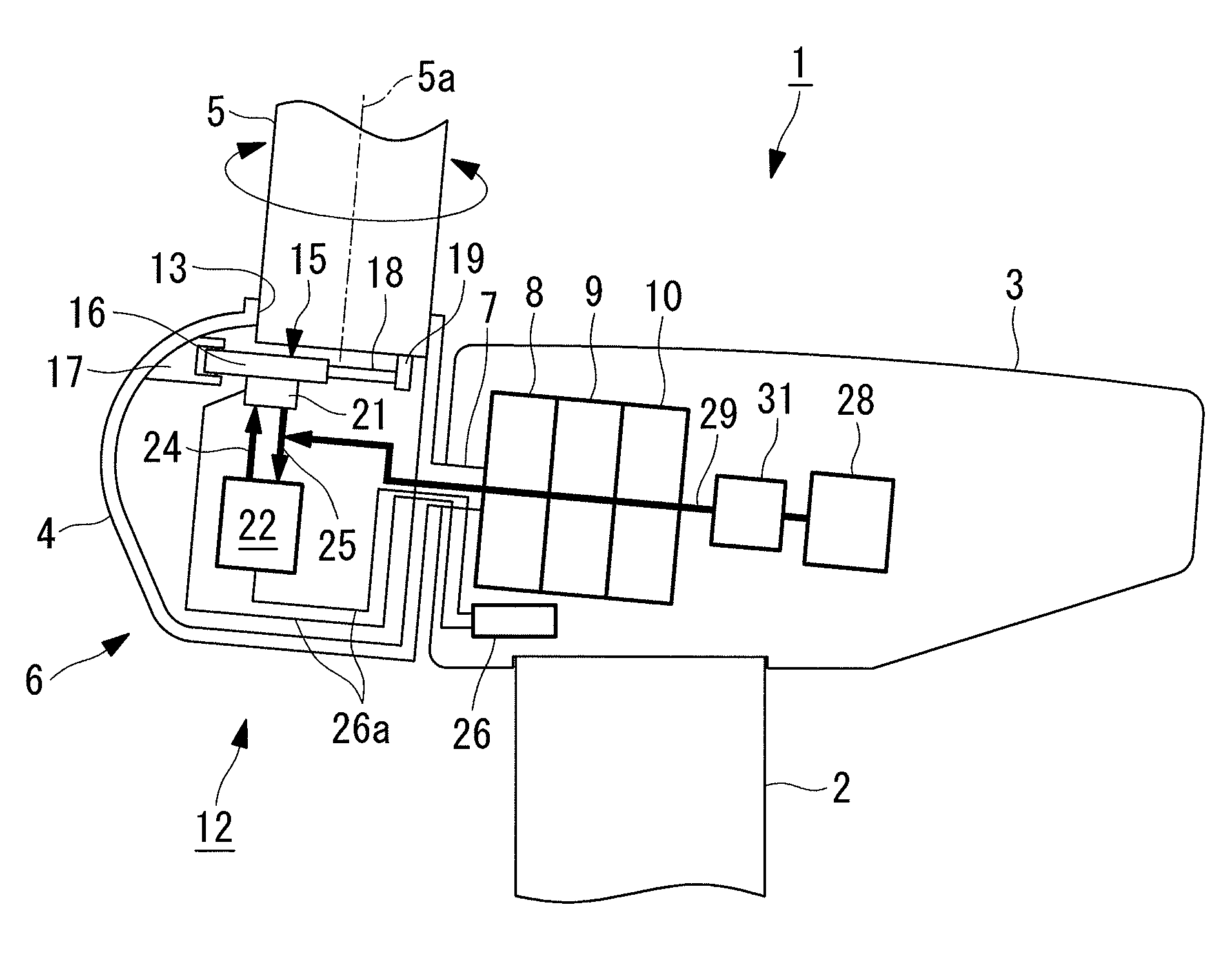
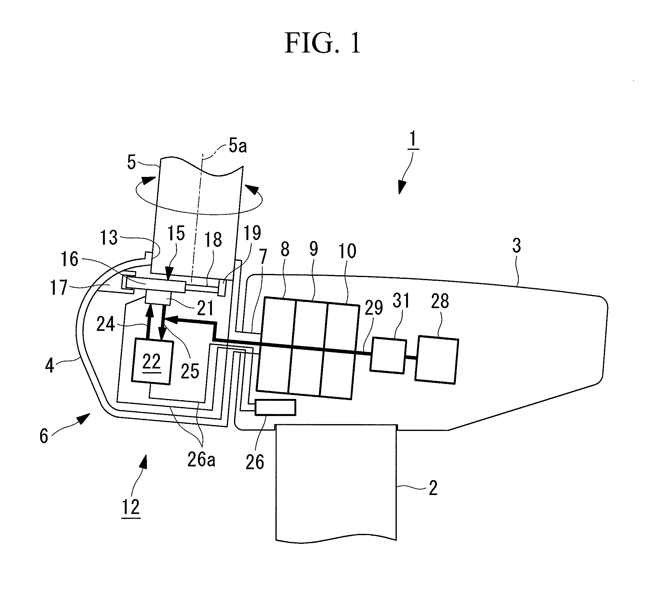
[0038]FIG. 1 is a side view showing an example of a wind power generator (wind turbine) to which a pitch driving unit for a wind-turbine rotor blade according to a first embodiment is applied. The wind power generator 1 is configured such that a nacelle 3 is supported at the upper end of a tower 2, in a manner allowing yawing, a rotor head 4 is supported by the nacelle 3 so as to be rotatable about a substantially horizontal rotation axis thereof, and a plurality of (for example, three) wind turbine blades 5 extending in a radiating pattern are mounted to the rotor head 4 to constitute a wind-turbine rotor blade 6.

[0039]The nacelle 3 accommodates a main bearing 8 that supports a rotating shaft 7 of the rotor head 4, a gearbox 9, and a generator 10. When the wind-turbine rotor blade 6 rotates upon receiving wind, the rotation of the rotating shaft 7 of the rotor head 4 is appropriately increased in speed and is transmitted to the generator 10, so that the generator 10 is driven to ge...

second embodiment

[0057]FIG. 4 is a side view of a wind power generator 41 to which a wind-turbine rotor blade pitch driving unit according to a second embodiment is applied. Since the wind power generator 41 is the same as the wind power generator 1 of the first embodiment shown in FIG. 1, except for the configuration of a pitch driving unit 42, the same reference signs are given to the components, and descriptions thereof will be omitted.

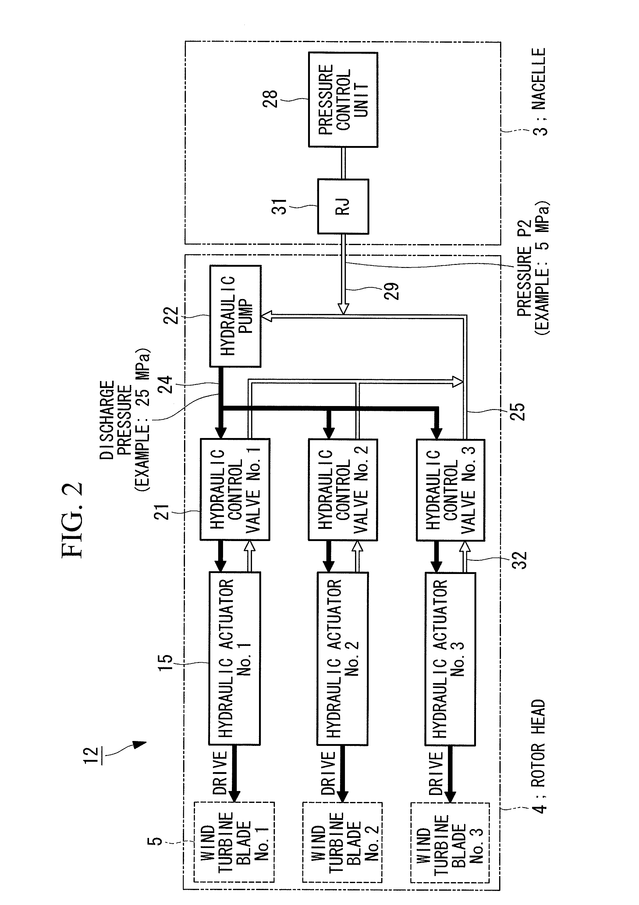
[0058]The pitch driving unit 42 is the same as the pitch driving unit 12 of the first embodiment in that it is equipped with the hydraulic actuators 15, the hydraulic pump 22, the high-pressure oil line 24, the low-pressure oil line 25, and the pressure control unit 43. However, it differs in that the pressure control unit 43 is accommodated in the rotor head 4. Specifically, the foregoing components 15, 22, 24, 25, and 43 that constitute the pitch driving unit 42 are all accommodated together in the rotor head 4.

[0059]The high-pressure oil line 24 and the low-pres...


PUM


Abstract

A pitch driving unit according to the present invention is equipped with hydraulic actuators that change the pitch angles of wind turbine blades; a hydraulic pump that supplies oil to the hydraulic actuators; a high-pressure oil line that guides the oil discharged from the hydraulic pump to the hydraulic actuators; a low-pressure oil line that returns the oil discharged from the hydraulic actuators to the hydraulic pump; and a pressure control unit that stores a surplus amount of the oil and that refills the low-pressure oil line with the oil so as not to generate negative pressure at an oil intake portion of the hydraulic pump, wherein the hydraulic actuators 15, the hydraulic pump, the high-pressure oil line, the low-pressure oil line, and the pressure control unit constitute a closed hydraulic circuit that does not open to the atmosphere, the closed hydraulic circuit being filled with the oil.

Description

CROSS REFERENCE TO RELATED APPLICATIONS[0001]This application is a continuation application of PCT / JP2011 / 070594 filed on Sep. 9, 2011, the contents of which is hereby incorporated by its reference.BACKGROUND OF THE INVENTION[0002]1. Field of the Invention[0003]The present invention relates to a pitch driving unit for a wind-turbine rotor blade in which the pitch angles of wind turbine blades are changed by hydraulic actuators, and to a wind power generator equipped with the same.[0004]2. Description of Related Art[0005]Standard propeller-type wind power generators are equipped with a wind-turbine rotor blade in which a plurality of wind turbine blades are mounted to a rotor head serving as a rotation center. These wind power generators are configured in such a manner that the wind-turbine rotor blade is rotatably supported by a nacelle that is supported at the upper end of a tower in a manner allowing yawing, and the wind-turbine rotor blade rotates by receiving wind power, so that...

Claims


Application Information

Patent Timeline
Patent Type & Authority Applications(United States)
IPC IPC(8): F03D7/04
CPCF03D7/0224Y02E10/723F05B2270/604Y02E10/72
Inventor NUMAJIRI, TOMOHIRO
Owner MITSUBISHI HEAVY IND LTD
Why Eureka
Try Eureka