
Rubber dam

a rubber-dam and a technology of rubber-dams, applied in the field of rubber-dams, can solve the problems of inability to carry out any treatment of gingival margins with the known rubber-dam, the use of dentists is not common, and the treatment of gingival margins is not possibl

Inactive Publication Date: 2003-11-18
HORVATH DR DOMONKOS +1
View PDF15 Cites 15 Cited by
  • Summary
  • Abstract
  • Description
  • Claims
  • Application Information

AI Technical Summary

Benefits of technology

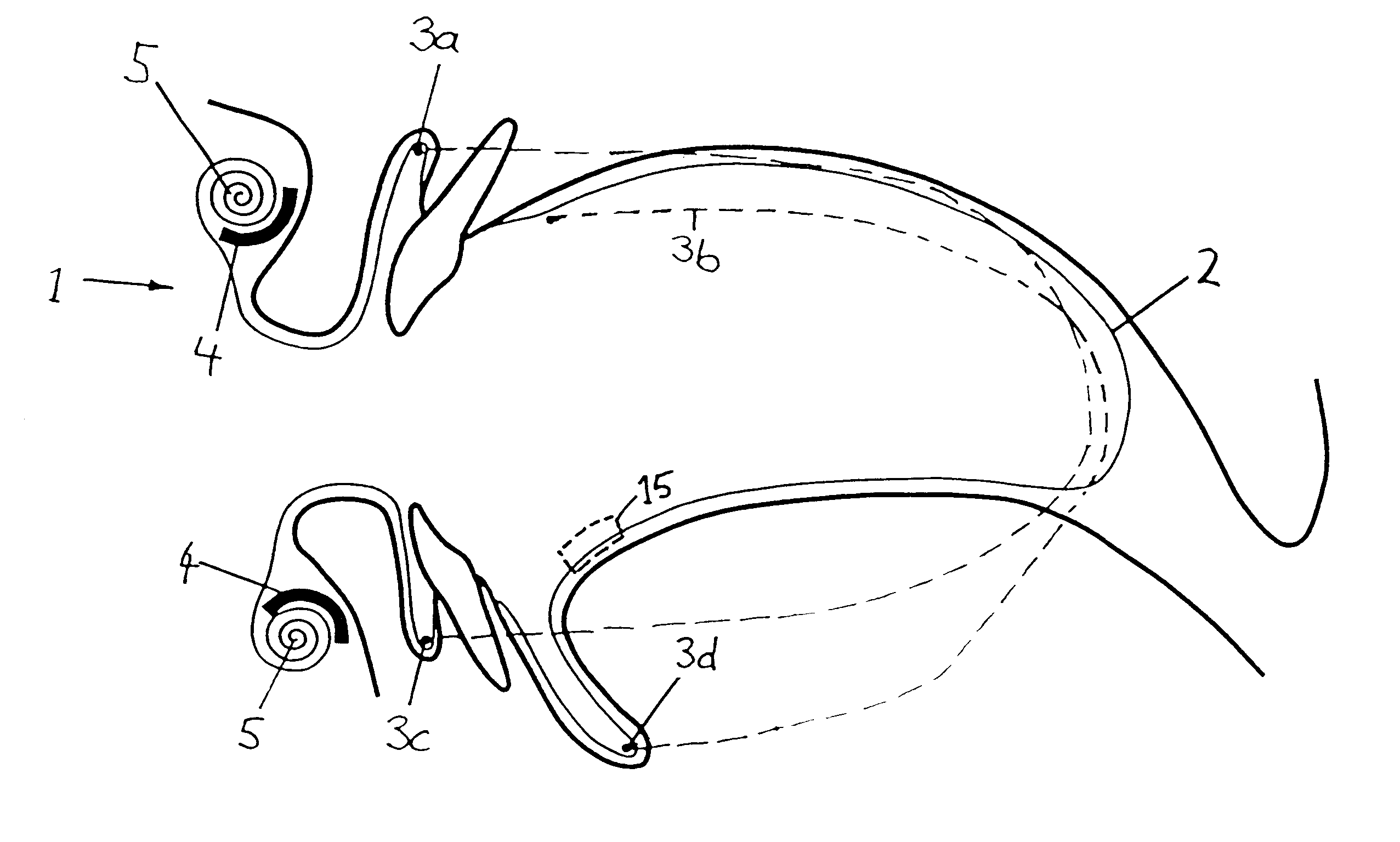
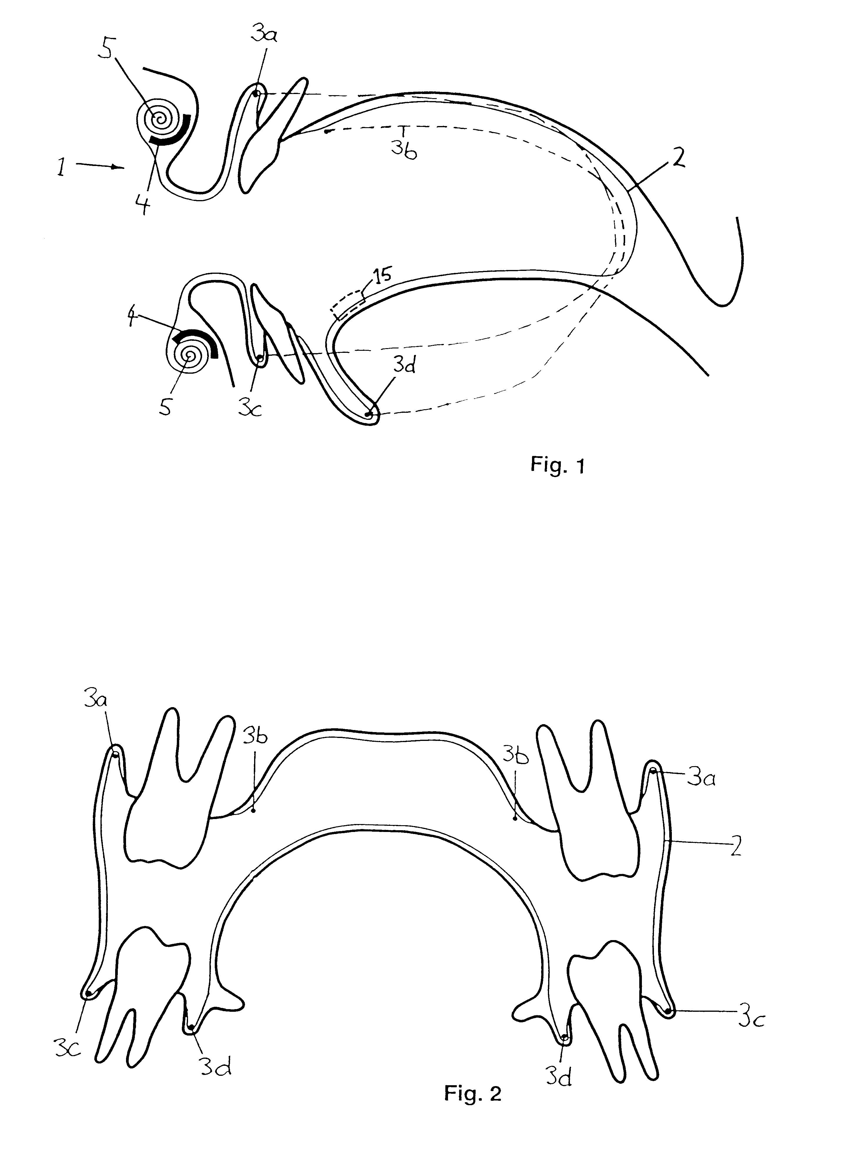
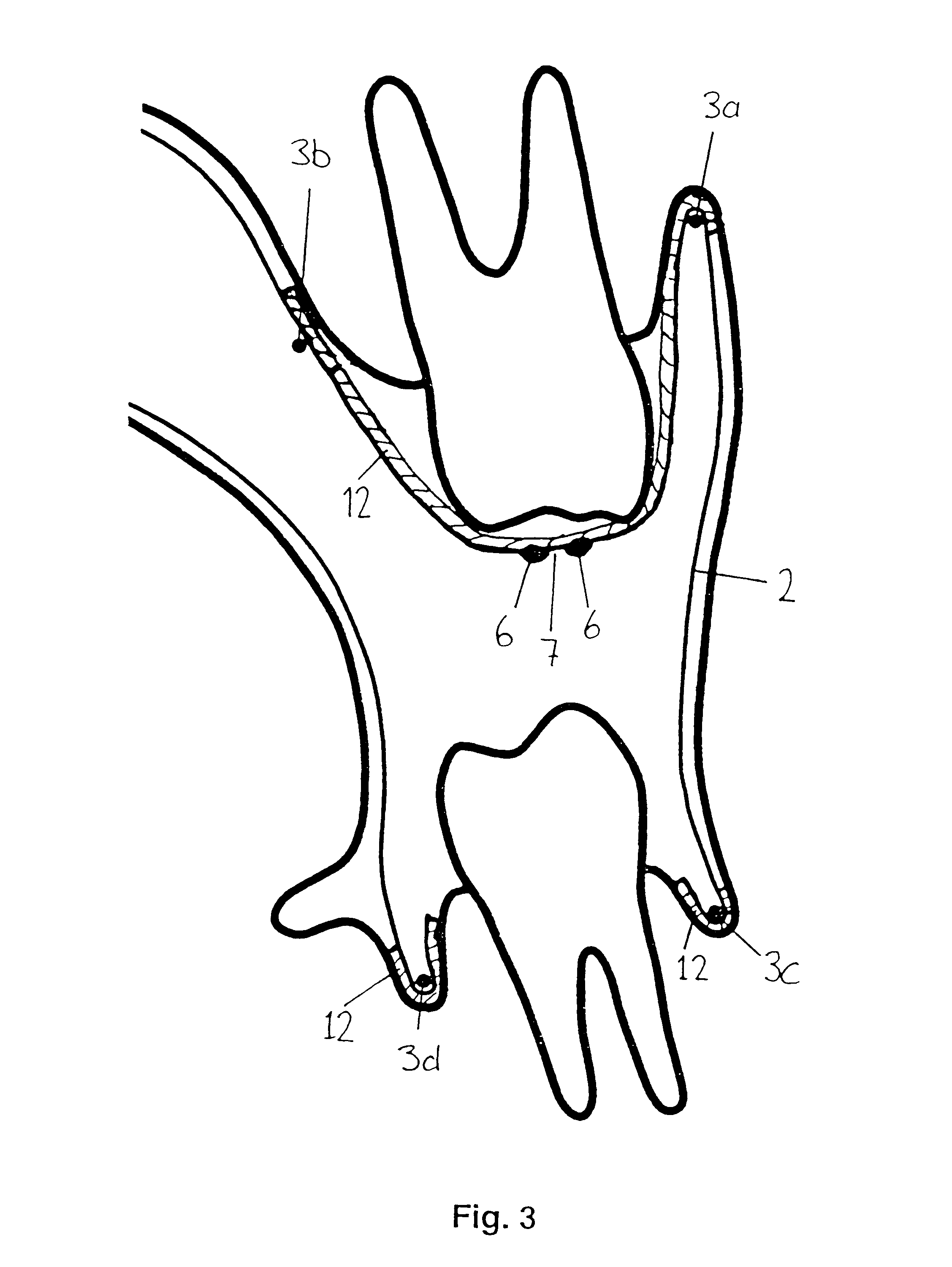
Since affixing the rubber-dam requires small retaining forces only, affixing is made easier and conventional attaching clamps, which can damage the teeth, are not required. Instead of this, it becomes possible to uncover not only the teeth but also the gingiva in the working area, such that the neck of the tooth and the adjacent gingiva become accessible for treatment by the dentist. This is of central importance for modern dental treatment.
In a further preferred embodiment at least one groove is arranged in an incisal / occlusal area of the cover means, which marks the place where the rubber-dam must be cut open in order to gain access to the corresponding teeth. In this way, an accurate opening of the cover means becomes possible.

Problems solved by technology

Even though the rubber-dam could be of largest significance for modern dental treatments, it is only seldom used by dentists.
Treatments in the area of the gingival margin are hardly possible or only under traumatization of the marginal sulcus.
Treatments that involve the gingiva cannot be carried out with the known rubber-dam at all.

Method used


Image

  • Rubber dam
  • Rubber dam
  • Rubber dam

Examples


third embodiment

FIG. 8 shows a rubber-dam 1 according to the invention consisting of a cover means 2 and the affixing device 3. In this case, the cover means 2 is a planar foil made of raw latex or another suited material, which is shown in the figure in its planar state.

The affixing device 3 comprises a frame of two plastically deformable retaining members 103a and 103b and two elastic connecting members 103c and 103d, which are applied flat to cover means 2 and serve as a holder means. The frame formed by members 103a to d encloses a partial surface 108 of the cover means 2, on which a dotted line 109 with a cut to be applied is drawn. A rubber-dam frame 104 is provided on the outer margin of the cover means 2, which keeps the rubber sheet stretched and can be deformed such that it covers the open mouth area without hampering the dentist or patient.

On the side of the cover means 2 opposite to the holder means 103a to d, a glue layer has been applied in the area of the holder means and the limited...

second embodiment

FIG. 12 shows a plastic clip 10. It is also substantially shaped as a U and comprises holders 128, where notches 130 are formed. The notches 130 serve for receiving the cover means.

The plastic clips 10 of FIG. 11 and 12 are fastened to a tooth by means of a suited cement or glue. However, they can also be shaped such that they can be pushed onto a tooth and hold the same elastically.

FIG. 13 shows a third embodiment of a clip. This clip is anatomically adapted to the shape of the tooth. It can be prefabricated or consist of a quickly hardening plastic material, which is shaped to the tooth and then hardened. If necessary, a glue can be applied between the clip 10 and the tooth. The cover means is glued to the outer side of the clip.

In FIGS. 14 and 15 an alternative embodiment of the cover means 2 is shown. It possesses a bellows area 140 in the area of the tooth rows, which is folded accordion-like. If it is cut open, as shown in FIG. 4, it retracts and releases the operating area.

It...


PUM


Abstract

The rubber-dam preferably has bag shape or it can be brought into bag shape by means of suited holder means, such that it can be well placed into the oral cavity. On its forward end it is rolled up and stretched onto a rubber-dam frame. The cover means of the rubber-dam can be cut open in the operating field. For sealing against gingiva, dental clips or teeth, it is provided with a glue coating or is suited for receiving an adhesive, respectively. The rubber-dam is easy to install, allows to isolate teeth and adjacent gingiva and requires no affixing clips traumatizing the teeth.

Description

This application claims the priority of the German patent applications 197 04 904 4, 197 22 218 8 and 197 33 712.0, filed on Feb. 10, 1997, May 28, 1997 and Aug. 4, 1997, and the disclosure of which is incorporated herein by reference in its entirety.The invention relates to a rubber-dam and a method according to the preamble of the independent claims.In dentistry, a rubber-dam is an aid for dental treatments that allows an isolation and thereby to keep the teeth to be treated dry. By this isolation the danger of infection in the area of the treated tooth is reduced as well. Synonymous terms are rubber dam, stretching rubber (Spanngummi), rubber flap (Gummilappen), rubber plate (Gummiplatte), rubber cloth (Gummituch), etc.STATE OF THE ARTSince the year 1864 it has been known to puncture a rubber cloth and to pull it over the tooth such that the edge of the hole in the rubber cloth abuts on the hard tooth and the rubber cloth covers the oral mucosa while the upper part of the tooth r...

Claims


Application Information

Patent Timeline
IPC IPC(8): A61C5/00A61C5/12A61C19/00A61C5/82
CPCA61C5/122A61C5/82
Inventor HORVATH, DOMONKOSLUTZ, FELIX
Owner HORVATH DR DOMONKOS
Learn More