Inflatable reflector antenna for space based radars

a space-based radar and reflector technology, applied in the field of antenna systems, can solve the problems of heavy metal mesh design, bulky, difficult to package and deploy, and general cost to construct, and achieve the effect of reducing the cost of construction

Inactive Publication Date: 2003-11-18
RAYTHEON CO
View PDF14 Cites 47 Cited by
  • Summary
  • Abstract
  • Description
  • Claims
  • Application Information

AI Technical Summary

Problems solved by technology

Space deployable antenna structures include metal mesh designs that are heavy, bulky, difficult to package and deploy, and generally expensive to construct.
Further, such mesh antennas would be difficult to implement as large antennas.
Known inflatable antenna structures have an antenna profile that tends to change, which impairs the properties of the antenna.

Method used


Image

  • Inflatable reflector antenna for space based radars
  • Inflatable reflector antenna for space based radars
  • Inflatable reflector antenna for space based radars

Examples


Embodiment Construction

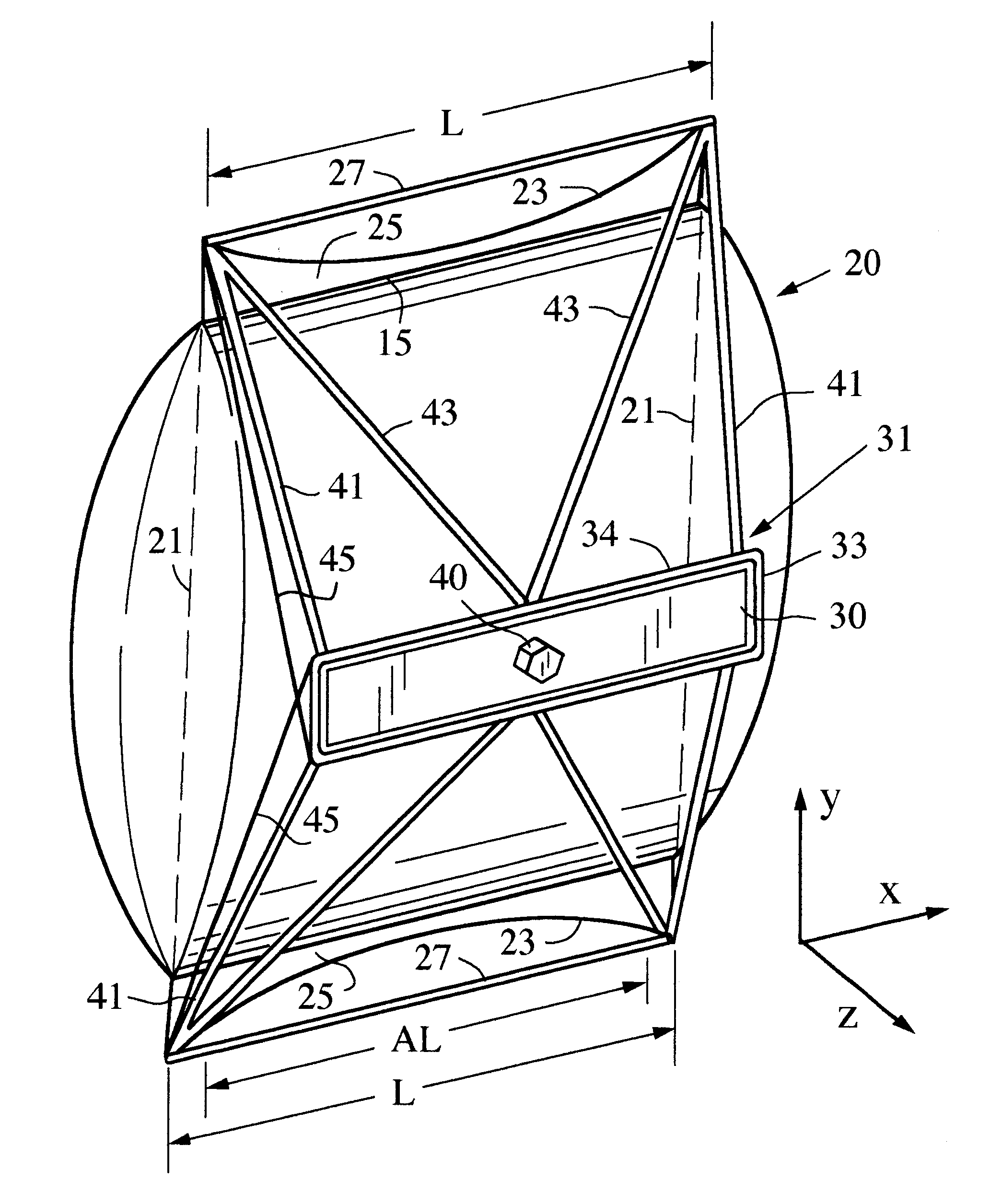
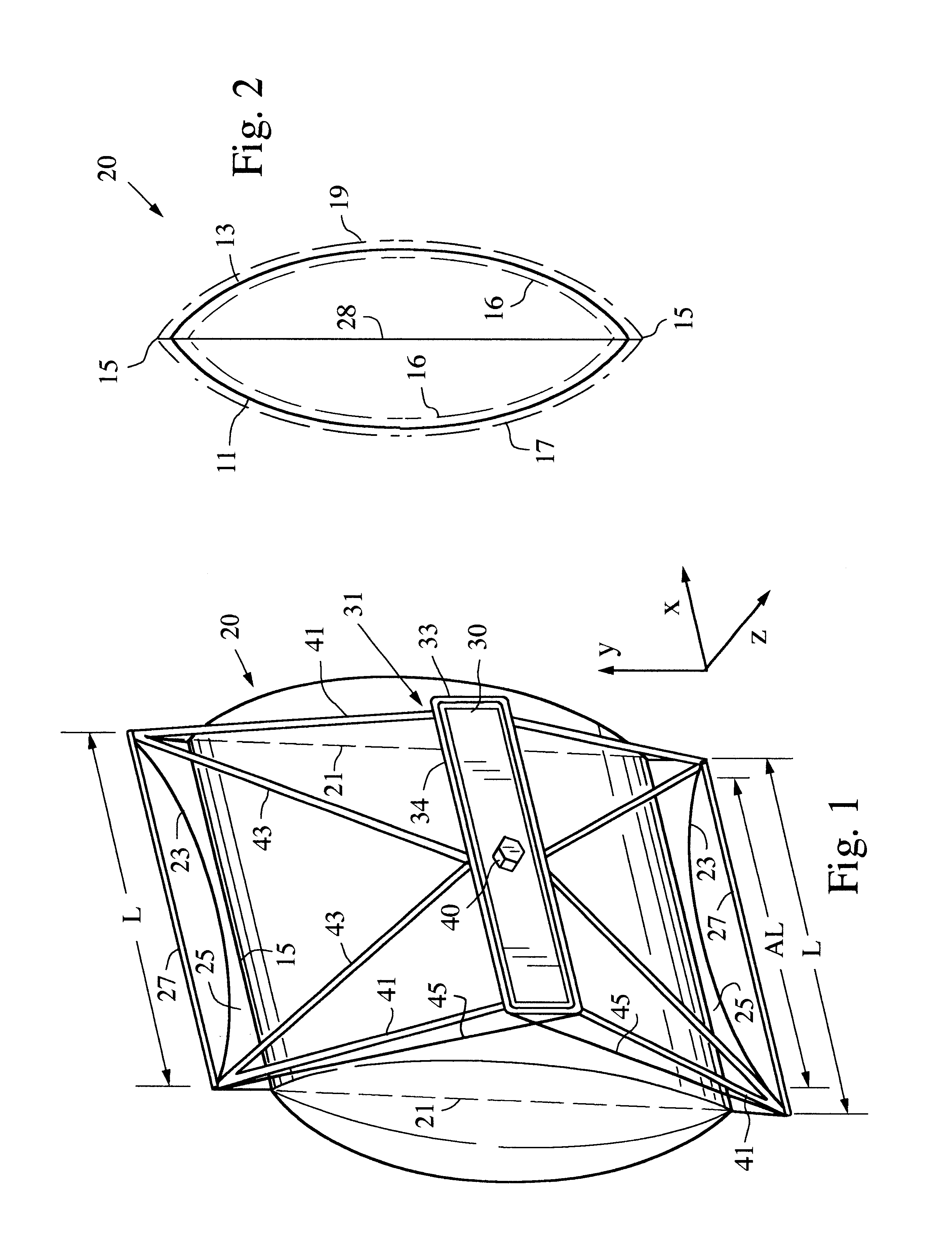
FIG. 1 illustrates an exemplary embodiment of an inflatable antenna structure in accordance with aspects of the invention. FIG. 1 is a schematic perspective view of an inflatable antenna structure that generally includes a pillow shaped inflatable envelope 20 formed of a thin flexible RF transparent plastic membrane, such as 0.3 mil thick Kapton (TM), and having a rear curved wall 11 and a front curved wall 13 (FIG. 2). The shape of the inflatable envelope is maintained by inflating gas and a catenary and strut frame as described further herein. An X-band and L-band feed array 30 and a bus 40 are supported in front of the front curved wall 13.

Referring now to FIG. 2, an RF transparent, high emissivity black coating 16, such as an ink coating, is disposed on the inside of the rear and front walls 11, 13 to lower thermal gradients over the reflector enough such that wall thermal expansion variations are low enough for acceptable reflector surface accuracy and therefore acceptable RF p...


PUM


Abstract

A space deployable antenna that includes an inflatable envelope, a cylindrical reflector formed on a wall of the envelope, a catenary support frame for maintaining the cylindrical shape of the cylindrical reflector, and a feed array support structure connected to the catenary support frame.

Description

TECHNICAL FIELD OF THE DISCLOSUREThe disclosed invention relates generally to antenna systems, and more particularly to an inflated reflector antenna structure.BACKGROUND OF THE DISCLOSURESpace deployable antenna structures include metal mesh designs that are heavy, bulky, difficult to package and deploy, and generally expensive to construct. Further, such mesh antennas would be difficult to implement as large antennas.Other space deployable antenna structures include inflatable antennas wherein an inflatable structure forms a reflective surface. Known inflatable antenna structures have an antenna profile that tends to change, which impairs the properties of the antenna.SUMMARY OF THE DISCLOSUREAn antenna is disclosed, which includes an inflatable flexible enclosed envelope having a curved wall transparent to RF, the curved wall ending at first and second opposing edges. An RF reflective coating is disposed on the curved wall. A catenary support frame supports the first and second e...

Claims


Application Information

Patent Timeline
Patent Type & Authority Patents(United States)
IPC IPC(8): H01Q1/28H01Q19/17H01Q1/27H01Q1/08H01Q19/10H01Q15/20H01Q15/16
CPCH01Q1/081H01Q1/082H01Q19/175H01Q15/163H01Q1/288
Inventor LEE, JAR J.DERBES, WILLIAMGORDON, JONATHAN D.
Owner RAYTHEON CO
Why Eureka
Try Eureka