
Platinum temperature sensor and its method of production

a temperature sensor and temperature sensor technology, applied in the field of platinum temperature sensors, can solve the problems of inability to meet all requirements, inability to adjust the resistor, and inability to meet the stability of the sensor,

Inactive Publication Date: 2003-11-25
BORGWARNER BERU SYST
View PDF18 Cites 34 Cited by
  • Summary
  • Abstract
  • Description
  • Claims
  • Application Information

AI Technical Summary

Benefits of technology

The present invention is based on the knowledge that ceramic materials, especially aluminium oxide Al.sub.2 O.sub.3 are insensitive to the above-described current induced decomposition, and thus this material that in addition is used in thin-film platinum temperature sensors as substrate material for the platinum film can advantageously also be used as protective material for capsulation of the platinum film layer. Thus, the problems of electrochemical decomposition and the connected deterioration of properties of the platinum temperature sensors are prevented, even when the protective cover is realized from a ceramic material.

Problems solved by technology

The field of use of the platinum temperature sensor, which is shown in FIG. 3 and which is implemented in thin-film technology, is normally limited to 600.degree. C.
By purposefully selecting the composition of the protective glaze 6, it has already been possible to find satisfactory solutions for some cases of use, whereas in very particular fields of application, e.g. in special cases of use in the field of automotive engineering, the results do not satisfy all requirements.
The resultant material migration has a negative influence on the properties of the platinum so that the stability of the sensors and, consequently, the measuring accuracy are impaired.
By purposefully selecting the composition of the protective glazes, improvements could be achieved to a certain extent, but it was impossible to find protective glazes that withstand the electrochemical decomposition by the measurement current in the case of continuous loads in a temperature range of 1,000.degree. C. or more than 1,000.degree. C.
On the other hand the inventive platinum temperature sensor supplies reliable measurement results even in the case of continuous loads in a high temperature range of for example 1000.degree. C. or more than 1000.degree. C., since the above-described disadvantageous decomposition phenomenons do not occur in the case of the inventive platinum film temperature sensor.

Method used


Image

  • Platinum temperature sensor and its method of production
  • Platinum temperature sensor and its method of production

Examples


Embodiment Construction

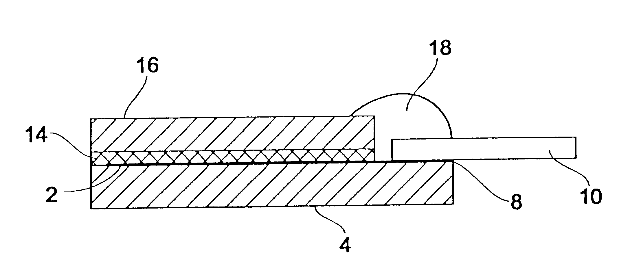
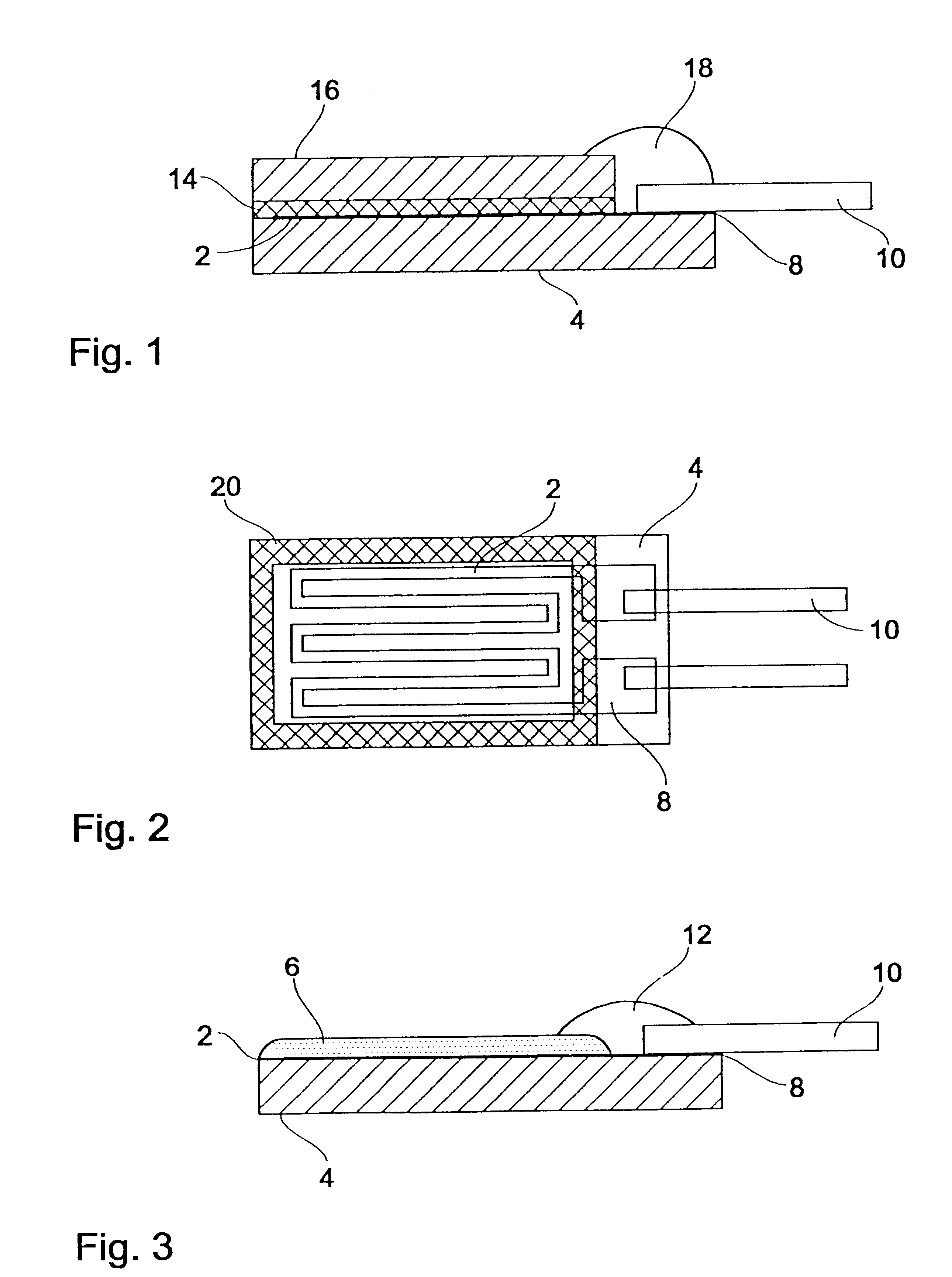
First, referring to FIG. 1, a first embodiment of a platinum temperature sensor according to the present invention is described in detail. The platinum temperature sensor comprises a ceramic substrate that consists of Al.sub.2 O.sub.3 in preferred embodiments on which a structured platinum layer is applied defining a platinum resistor trace 2 and connecting areas 8. A lead wire 10 can be electrically conductive connected with the connecting areas 8. A ceramic cover layer 16 which is also made from Al.sub.2 O.sub.3 in the preferred embodiments of the present invention is applied on the surface of the ceramic substrate 4 on which the platinum resistor trace is provided via a connecting layer 14, which consists also of Al.sub.2 O.sub.3 in the preferred embodiments of the present invention. Further, in FIG. 1 a glass ceramic 18 is illustrated that serves for fixing the lead wire.

It is preferable to use the same material for the cover layer 16 that is used for the ceramic substrate 4. Ho...


PUM


Abstract

A Platinum temperature sensor comprises a ceramic substrate and a platinum thin-film resistor applied to said ceramic substrate, a ceramic cover layer and a connecting layer generated from a ceramic green layer by pressure and temperature treatment. The ceramic cover layer is connected with the ceramic substrate in such a way via the connecting layer that the platinum thin-film resistor is sealingly encapsulated with regard to the environment.

Description

1. Field of the InventionThe present invention relates to a platinum temperature sensor and a method for producing the same, and in particular to a platinum temperature sensor in the case of which a platinum thin-film resistor, which is applied to a ceramic substrate, is used for temperature detection.2. Description of Prior ArtA known platinum temperature sensor is shown in FIG. 3. In this known platinum temperature sensor, a platinum thin-film resistor 2 is applied to a ceramic substrate 4 which normally consists of aluminium oxide Al.sub.2 O.sub.3. In the area in which the platinum thin-film resistor 2 is formed, a protective glaze 6 is provided on the surface of the ceramic substrate 4. The platinum layer, in which the platinum thin-film resistor 2 is normally formed in a meandering shape, is additionally patterned so as to include connecting areas 8 having lead wires 10 connected thereto in an electrically conductive manner for taking the sensor signal. For fixing the lead wire...

Claims


Application Information

Patent Timeline
IPC IPC(8): G01K7/18G01K7/16H01C7/02
CPCG01K7/18H01C17/02H01C7/006G01K7/183
Inventor ZITZMANN, HEINRICH
Owner BORGWARNER BERU SYST
Learn More