Plasma display panel driving method and plasma display panel apparatus capable of displaying high-quality images with high luminous efficiency
a technology of plasma display panel and driving method, which is applied in the direction of instruments, static indicating devices, etc., can solve the problems of lowering the quality of the image displayed, affecting the contrast of the whole panel, and further reducing the brightness of the whole panel
- Summary
- Abstract
- Description
- Claims
- Application Information
AI Technical Summary
Benefits of technology
Problems solved by technology
Method used
Image

Examples
first embodiment
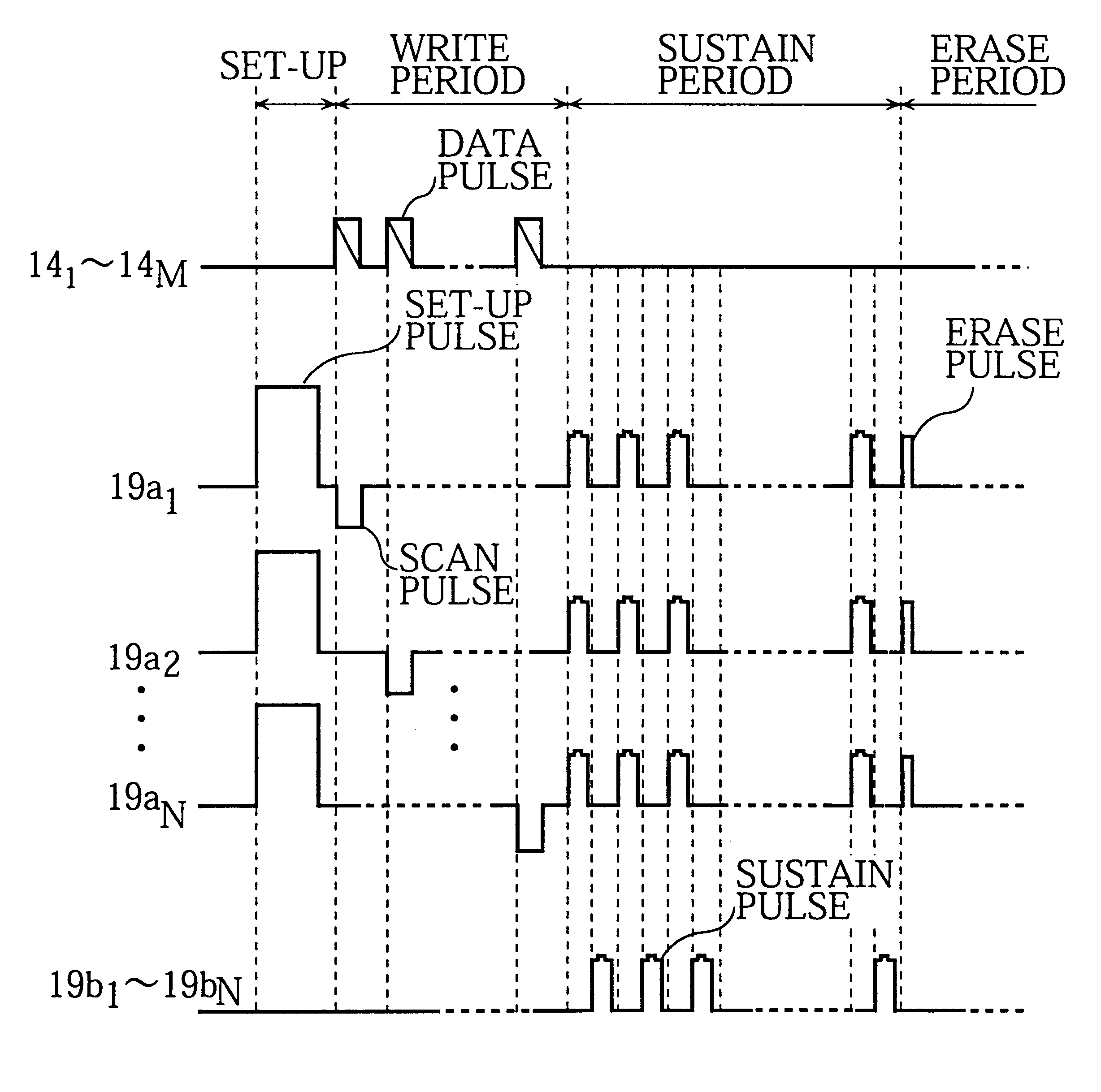
FIG. 8 is a time chart showing a PDP driving method relating to the present embodiment.
In the related art driving method shown in FIG. 4, the set-up pulses had a simple rectangular wave. In this embodiment, however, the set-up pulses use a staircase waveform that rises in two steps.
This kind of waveform is achieved by adding two pulse waveforms and applying them.
FIG. 9 is a block diagram of a pulse adding circuit which generates the staircase waveform.
The pulse adding circuit includes a first pulse generator 131, a second pulse generator 132 and a time-delay circuit 133. The first and second pulse generators 131 and 132 are connected in series using a floating ground method, and the output voltage of the two generators added.
FIG. 10A shows a situation in which the pulse adding circuit synchronizes first and second pulses to form a staircase waveform which rises in two steps.
The first pulse generated by the first pulse generator 131 is a wide rectangular wave and the second pulse gen...
experiment 1
A two-step rise waveform was used for the set-up pulses when driving a PDP. While driving was performed, the peak voltage V.sub.st and the pulse width t.sub.w remained fixed, but the t.sub.p to t.sub.w ratio and the (V.sub.st -V.sub.1)to V.sub.st ratio were changed to various values and the variations in contrast and brightness measured.
Each of the waveforms for the set-up pulses was generated by a given waveform generator and the voltage of this output was amplified by a high-speed high-voltage amplifier before being applied to the PDP.
Contrast was measured by igniting one part of the PDP to produce white color in a dark room and measuring the luminance ratio of the dark part to the light part.
FIG. 11 shows the results of this experiment, displaying the relation between the ratio t.sub.p to t.sub.w and the ratio (V.sub.st -V.sub.1) to V and contrast.
The shaded area in the drawing is the area in which contrast is high and variations in luminance caused by write defects are low; in o...
second embodiment
FIG. 12 is a time chart showing a PDP driving method relating to the present embodiment.
In the first embodiment, a two-step rising waveform was used for the set-up pulses, but in this embodiment a two-step falling waveform is used for the set-up pulse.
FIG. 13 shows a situation in which the pulse adding circuit adds first and second pulses to form a staircase waveform which falls in two steps.
The two-step falling waveform uses a pulse adding circuit like the one explained in the first embodiment and can be generated by adding a first pulse generated by the first pulse generator 131 and a second pulse generated by the second pulse generator 132.
Specifically, a pulse adding circuit like the one in FIG. 9, in which a first pulse generator and a second pulse generator are connected in series using a floating ground method, is used. As shown in FIG. 13A, a first pulse with a wide rectangular wave is raised by the first pulse generator 131 at almost the same time as a second pulse with a n...
PUM
 Abstract
Description
Claims
Application Information
 - Generate Ideas
- Intellectual Property
- Life Sciences
- Materials
- Tech Scout
- Unparalleled Data Quality
- Higher Quality Content
- 60% Fewer Hallucinations
Browse by: Latest US Patents, China's latest patents, Technical Efficacy Thesaurus, Application Domain, Technology Topic, Popular Technical Reports.
© 2025 PatSnap. All rights reserved.Legal|Privacy policy|Modern Slavery Act Transparency Statement|Sitemap|About US| Contact US: help@patsnap.com