Resonance type switching power supply unit

a power supply unit and resonance technology, applied in the direction of electric variable regulation, process and machine control, instruments, etc., can solve the problem of increasing switching loss

Inactive Publication Date: 2003-11-25
SONY CORP
View PDF3 Cites 60 Cited by
  • Summary
  • Abstract
  • Description
  • Claims
  • Application Information

AI Technical Summary

Problems solved by technology

That is, since the switching element 5A is forcibly turned off to cut the current, which is going to flow at the self-resonance point denoted as IQ.sub.1, the turning-off operation at a timing when the current value is large results in an increased switching loss.

Method used


Image

  • Resonance type switching power supply unit
  • Resonance type switching power supply unit
  • Resonance type switching power supply unit

Examples


Embodiment Construction

Embodiments of the present invention will be hereinafter described in detail with reference to attached drawings.

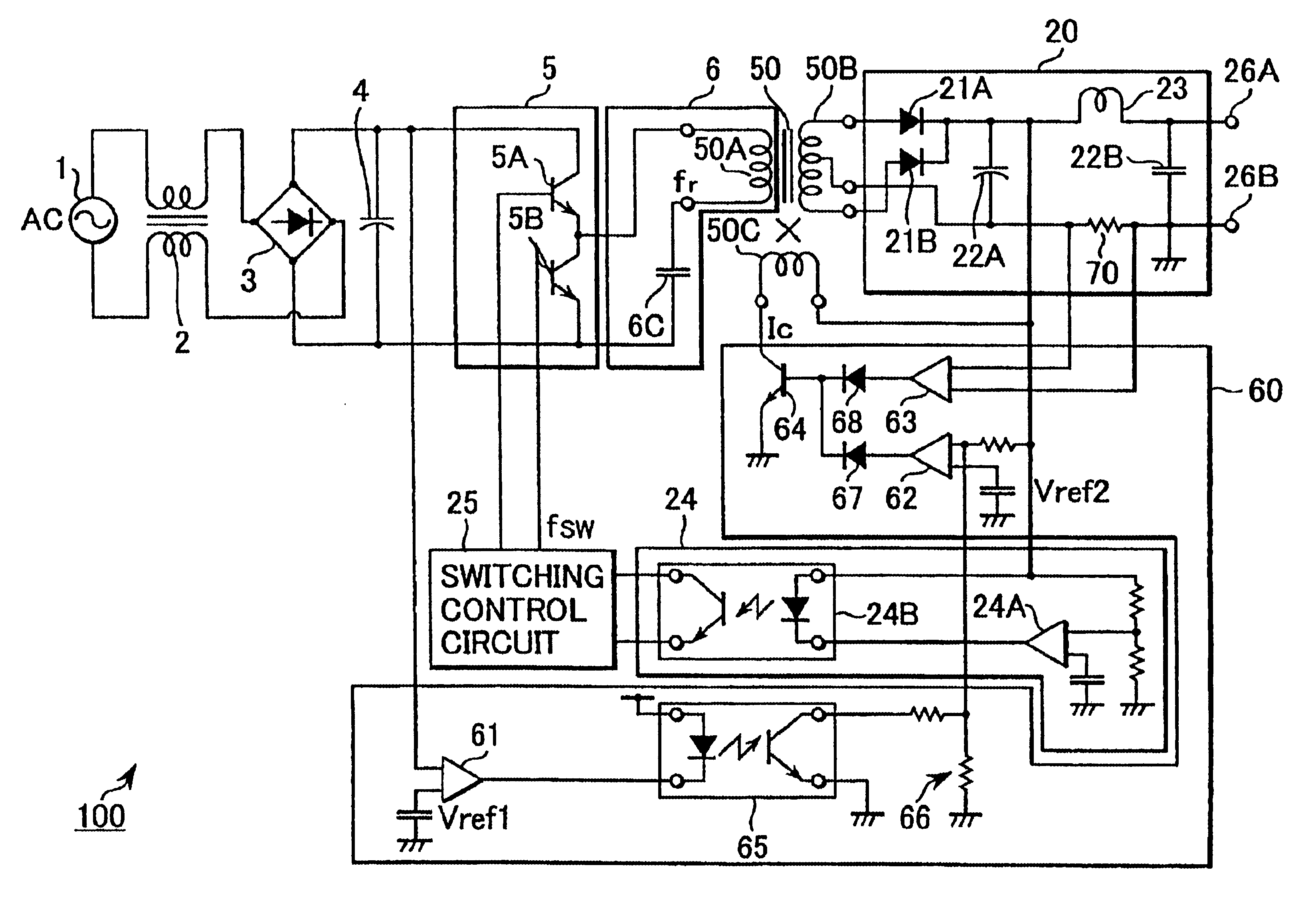
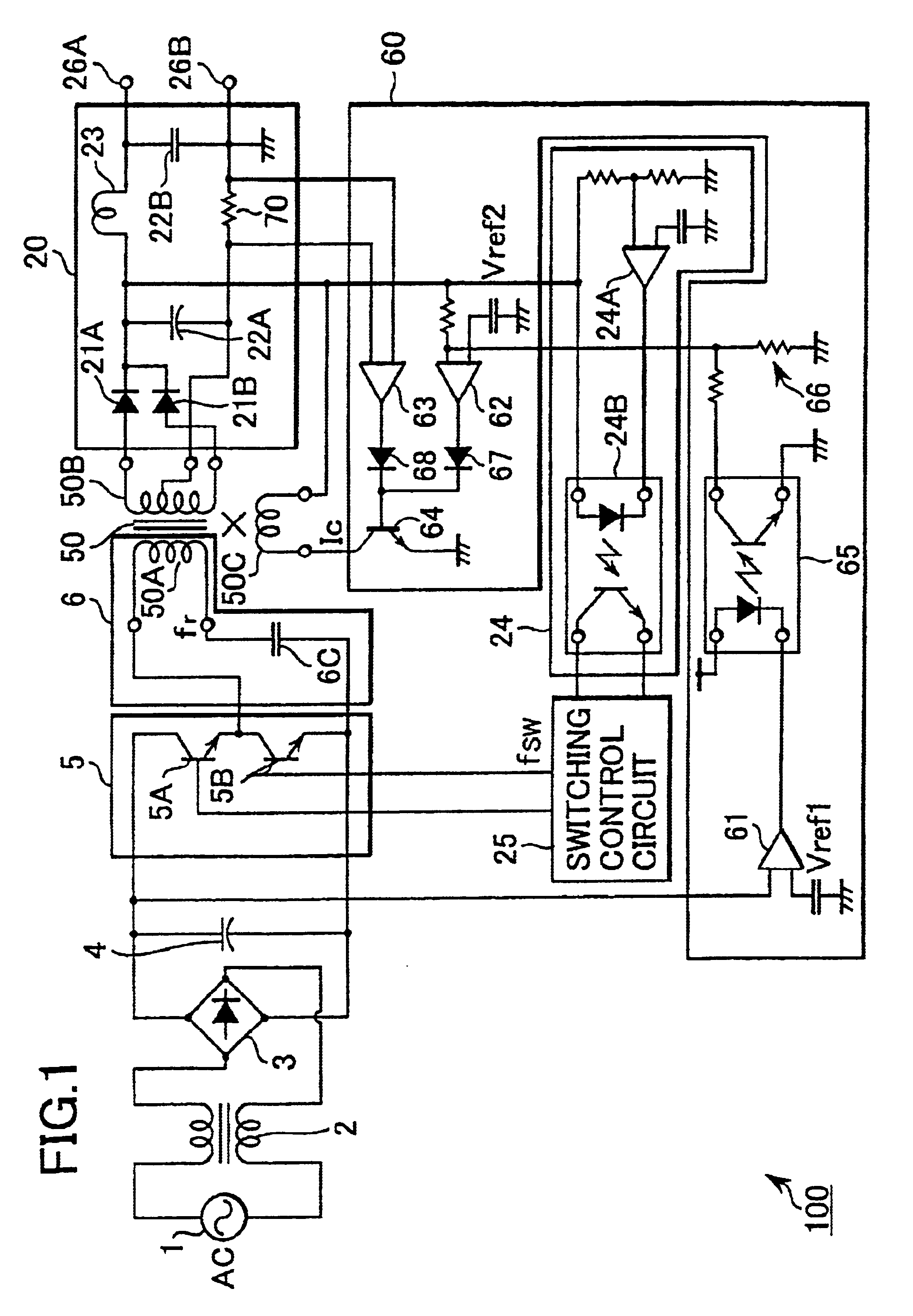
The resonance type switching power supply unit according to the present invention is arranged as shown in FIG. 1, for example.

A current resonance type switching power supply unit 100 shown in FIG. 1 is a unit in which the present invention is applied to the current resonance type switching power supply unit 200 shown in FIG. 8. That is, the converter transformer 10 in which the leakage inductance is fixedly settled is replaced with a converter transformer 50 in which a leakage inductance is variably settled. Also, the current resonance type switching power supply unit 100 is provided with a control circuit 60 for controlling the leakage inductance of the converter transformer 50.

In the current resonance type switching power supply unit 100 shown in FIG. 1, like components corresponding to those constituting the current resonance type switching power supply unit 200 shown ...


PUM


Abstract

An object of the present invention is to create the optimum resonating condition to constantly decrease switching losses. A converter transformer capable of varying the leakage inductance is employed as a converter transformer, and a control circuit is arranged to detect an input voltage applied to a switching circuit and a voltage drop brought about in a current detecting resistor which allows a load current to flow. Thus, the leakage inductance of the converter transformer can be controlled.

Description

The present document is based on Japanese Priority Document JP 2000-391186, filed in the Japanese Patent Office on Dec. 22, 2000, the entire contents of which being incorporated herein by reference.1. Field of the InventionThe present invention relates to a resonance type switching power supply unit having a switching circuit for carrying out a switching operation on an inputted direct current, a converter transformer supplied with a switched output from the switching circuit, a resonator including a coil of the converter transformer as a resonator element, a rectifier for rectifying an output of the converter transformer and supplying the resultant output to a load connected to the resonance type switching power supply unit, and a switching controller for controlling the switching frequency of the switching circuit depending on the rectified output deriving from the rectifier.2. Description of Related ArtA switching power supply unit has been utilized in a situation in which a comm...

Claims


Application Information

Patent Timeline
Patent Type & Authority Patents(United States)
IPC IPC(8): H02M3/24H02M3/337H02M3/28
CPCH02M3/3376Y02B70/1441H02M2007/4818H02M7/4818Y02B70/10
Inventor KOSHITA, WAKOKOBORI, KATSUMI
Owner SONY CORP
Why Eureka
Try Eureka