Method of casting a product

a technology of product casting and casting method, which is applied in the direction of gearing, pistons, and stators, etc., can solve the problems of poor machinability of product casting as cast, high production cost, and deterioration of machinability, and achieve the effect of easy and inexpensive casting

Inactive Publication Date: 2003-12-23
AHRESTY
View PDF1 Cites 1 Cited by
  • Summary
  • Abstract
  • Description
  • Claims
  • Application Information

AI Technical Summary

Benefits of technology

It is a first object of the present invention to provide a method of casting a product with a surface having a required function such as wear resistance that is formed easily and inexpensively by means of a normally known pressure casting process.
Further, it is a second object of the present invention to provide a method of casting a product with a function selecting layer of sufficient thickness formed on the surface even when very fine function selecting materials are used, and wherein the machinability of the product as cast is excellent.
Although there is no particular restriction to the shape of the particles of these function selecting materials used, it is preferable that the particle size is in a range of 1 .mu.m to 50 .mu.m and it is preferable that the size is uniformly and particularly in a range of 1 .mu.m to 40 .mu.m when the product as cast is subjected to machining such as cutting. In this case although there is no problem if the size of the function selecting material is small, when the size is 50 .mu.m or larger, the machinability of the product as cast is reduced which is not preferable.
Further, as the coating metal material used in the present invention, there is a metal material comprising one or two selected from the group consisting of aluminum or its alloy, magnesium alloy, zinc alloy, copper or its alloy, iron or its alloy and the like. A metal material of the same kind or the same group as that of the casting metal material is preferably used. Specifically, when, for example, an aluminum alloy is used as the casting metal material, aluminum or its alloy, magnesium alloy, zinc alloy etc. is used as the coating metal material, or when a magnesium alloy is used as the casting metal material, the magnesium alloy is used also as the coating metal material. In this way, a metal material of the same kind as that of the casting metal material or a metal material which is easy to make an alloy compatible with the casting metal material is used. Thereby, even when the intermediate material is formed in a granular shape and is formed into a metal preform, the intermediate material will not drop off from the surface of the cast product.
With regard to the shape of particle of the granular intermediate material, a polygonal shape having irregularities on the surface is preferable to a spherical shape with smooth surface. When the granular intermediate material is formed of particles in a polygonal shape having irregularities on the surface, the mechanical bonding force bonding the granular intermediate material to the matrix (casting metal material) is improved, whereby the granular intermediate material is prevented from detaching from the cast product. FIG. 2 illustrates a schematic view representing the structure of the granular intermediate material.

Problems solved by technology

However, according to this method much restriction is imposed on the shape of the product, manufacturing steps are prolonged and the machinability of the product as cast is poor, giving rise to a disadvantage of very high production cost.
However, according to this conventional method, when the size of the wear resistant fine particles is increased, the machinability is deteriorated.
On the other hand, when the size of the wear resistant fine particles is decreased, the thickness of the wear resistant layer becomes very thin.
Moreover, when the metal is cast together with the wear resistant fine particles, there is a risk that the function of the cast product will not be achieved since a binder holding the wear resistant fine particles remains in the cast product and it is difficult to increase the thickness of the wear resistant layer.

Method used


Image

  • Method of casting a product
  • Method of casting a product
  • Method of casting a product

Examples


example 1

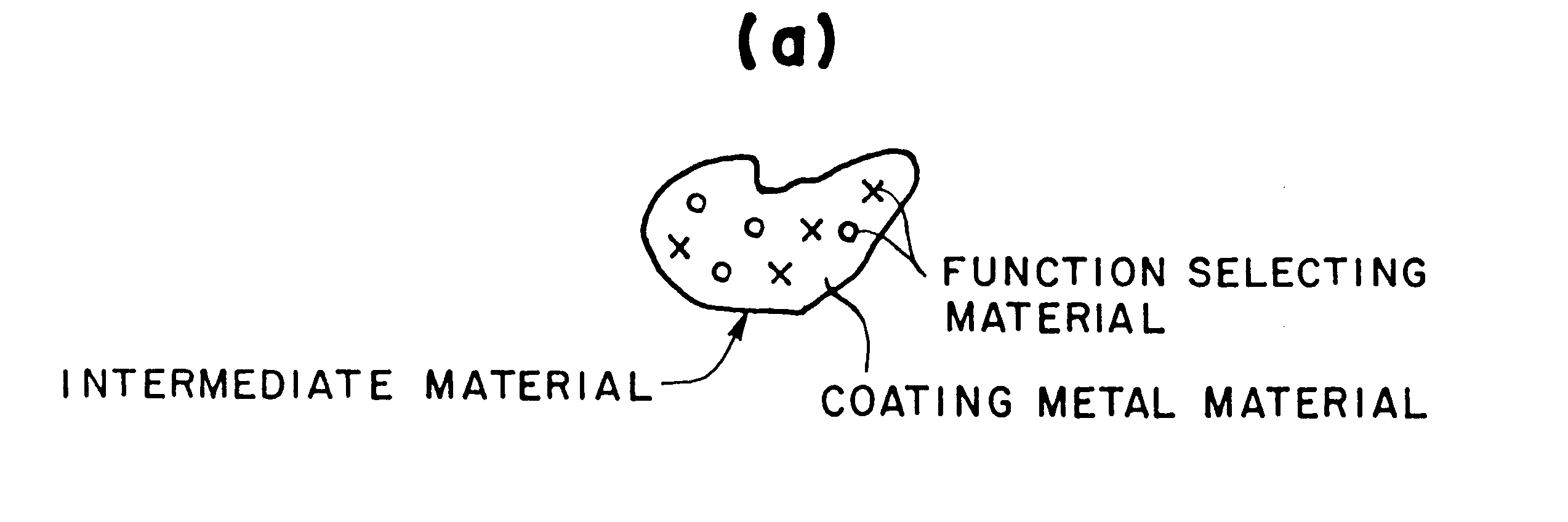
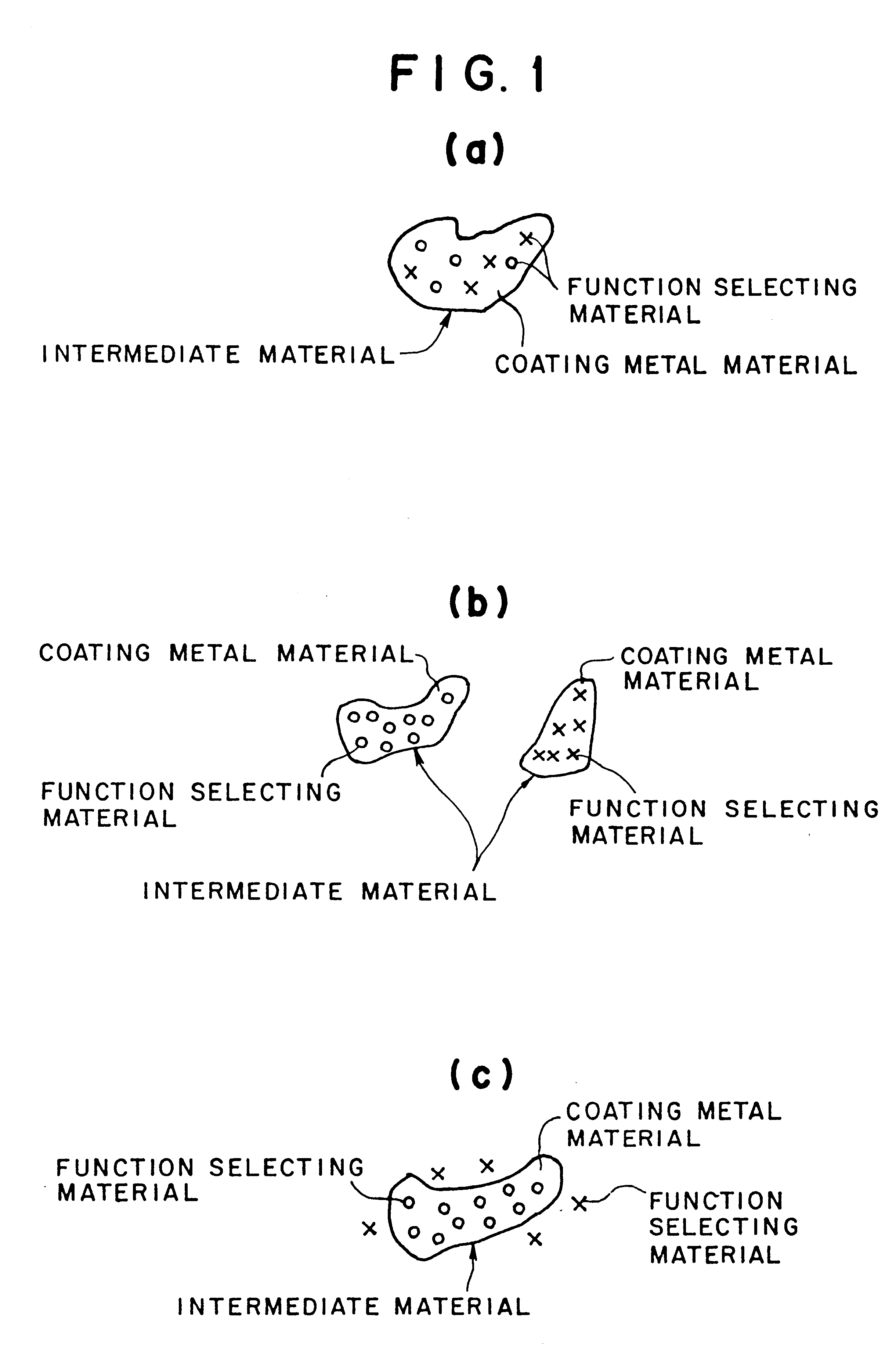
SiC having a uniformly distributed particle size of around 5 .mu.m was mixed into a molten aluminum alloy (ADCl2) by 10% by weight, dispersed in the liquid phase and converted into a granular intermediate material having a uniformly distributed particle size of 200 (through) to 300 .mu.m through the atomization process. 1200 g of the intermediate material was kneaded by adding a solution in which 500 g of polyvinyl acetate resin was dissolved in 600 g of methanol. The intermediate material was coated on the surface of a previously formed shell core made of zircon sand by a thickness of approximately 4 mm, the preset core was installed at a predetermined location of a mold cavity and a cylinder block was cast by the die-cast process using the aluminum alloy (ADCl2). The casting pressure was set to 50 MPa.

Then, the cast product was taken out from the mold, the preset core was taken out from the cast product and thereafter, the thickness of the resulting function selecting layer (wear ...

example 2

A granular intermediate material having a uniformly distributed particle size of around 300 .mu.m in which primary crystal silicon having a uniformly distributed particle size of around 10 .mu.m was precipitated through the atomization process, was prepared by using a molten metal of Al-20% silicon alloy, 300 g of the intermediate material was added with 13 g of phenolic resin and the intermediate material was kneaded for about 1 minute. The intermediate material was adheringly coated on the surface of a preset core made of iron, the preset core was installed at a predetermined location in a mold cavity, the casting was performed as in Example 1 and the thickness and the like of the resulting function selecting layer (wear resistant layer) formed on the surface of the cast product at a portion thereof where the preset core had been disposed, were measured.
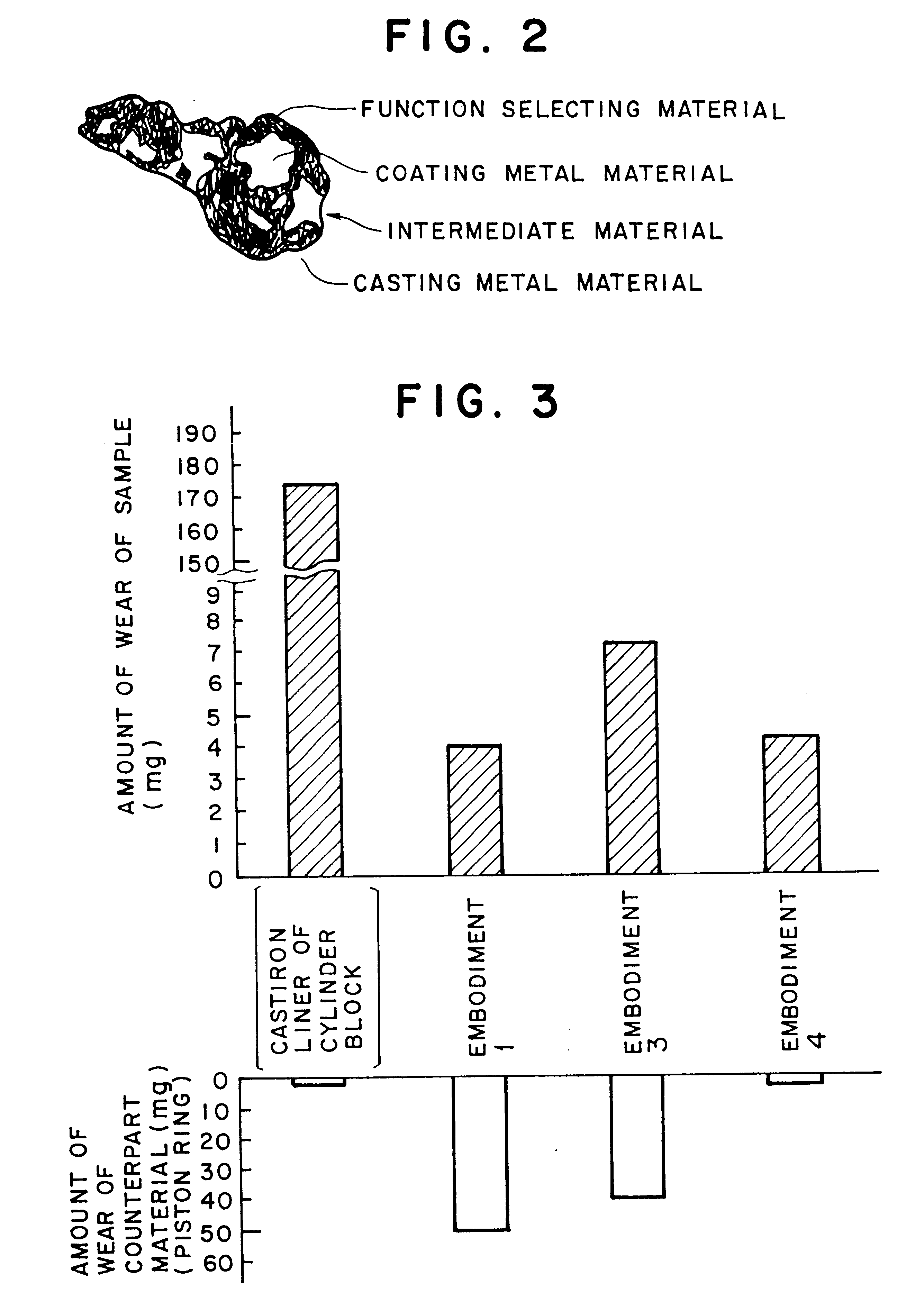
example 3

A granular intermediate material having a uniformly distributed particle size of around 300 .mu.m added with phenolic resin, was adheringly coated on the surface of a preset core made of iron and the casting was performed as in Example 1 except using SiC having a uniformly distributed particle size of around 10 .mu.m, the thickness of the resulting function selecting layer (wear resistant layer) formed on the surface of the cast product at a portion thereof where the preset core had been disposed, was measured and the wear resistance test was carried out.


PUM

PropertyMeasurementUnit
sizeaaaaaaaaaa
sizeaaaaaaaaaa
particle sizeaaaaaaaaaa

Abstract

An intermediate material is formed by coating at least a half of the surface of a function selecting material having at least one of physical property values that are different from those of a casting metal material forming a cast product with a coating metal material and the casting metal material is cast together with the intermediate material to form a composite body in casting the product.

Description

Field of the Invention and Related Art StatementThe present invention relates to a method of casting a product.It is often not necessary for the whole of a cast product to have a function that is required for only a part of the product. For example, an abrasive face of the cylinder portion in an engine block requires high wear resistance; however, the wear resistance is not required for the other portions. Therefore, it is sufficient in the cast product that only the necessary portion or the surface has the required function.In such a case it has been conventionally proposed as a method of adding the wear resistance to a portion of a cast product, for example, to set a preform comprising alumina, silicon nitride, silicon carbide or whiskers of these in a fiber form in a mold cavity and to force a molten metal into the mould cavity and into gaps among respective fibers. However, according to this method much restriction is imposed on the shape of the product, manufacturing steps are ...

Claims


Application Information

Patent Timeline
Patent Type & Authority Patents(United States)
IPC IPC(8): B22D19/08C22C1/10
CPCB22D19/08C22C1/1042C22C1/1036
Inventor FUKAI, SHIGEKIAOYAMA, SHUNZO
Owner AHRESTY
Why Eureka
Try Eureka