
Seat load measuring apparatus
a load measuring and seat technology, applied in the direction of force/torque/work measurement apparatus, instruments, tractors, etc., can solve the problems of increased production costs, troublesome mounting of sensor plates to the body of load sensors, and inability to effectively restrain the occupant in relation to the inertial force acting on the occupant, etc., to achieve improved compatibility and more efficient production
- Summary
- Abstract
- Description
- Claims
- Application Information
AI Technical Summary
Benefits of technology
Problems solved by technology
Method used
Image

Examples
Embodiment Construction
[0042] One of many embodiments of the present invention will be described below with reference to the drawings.
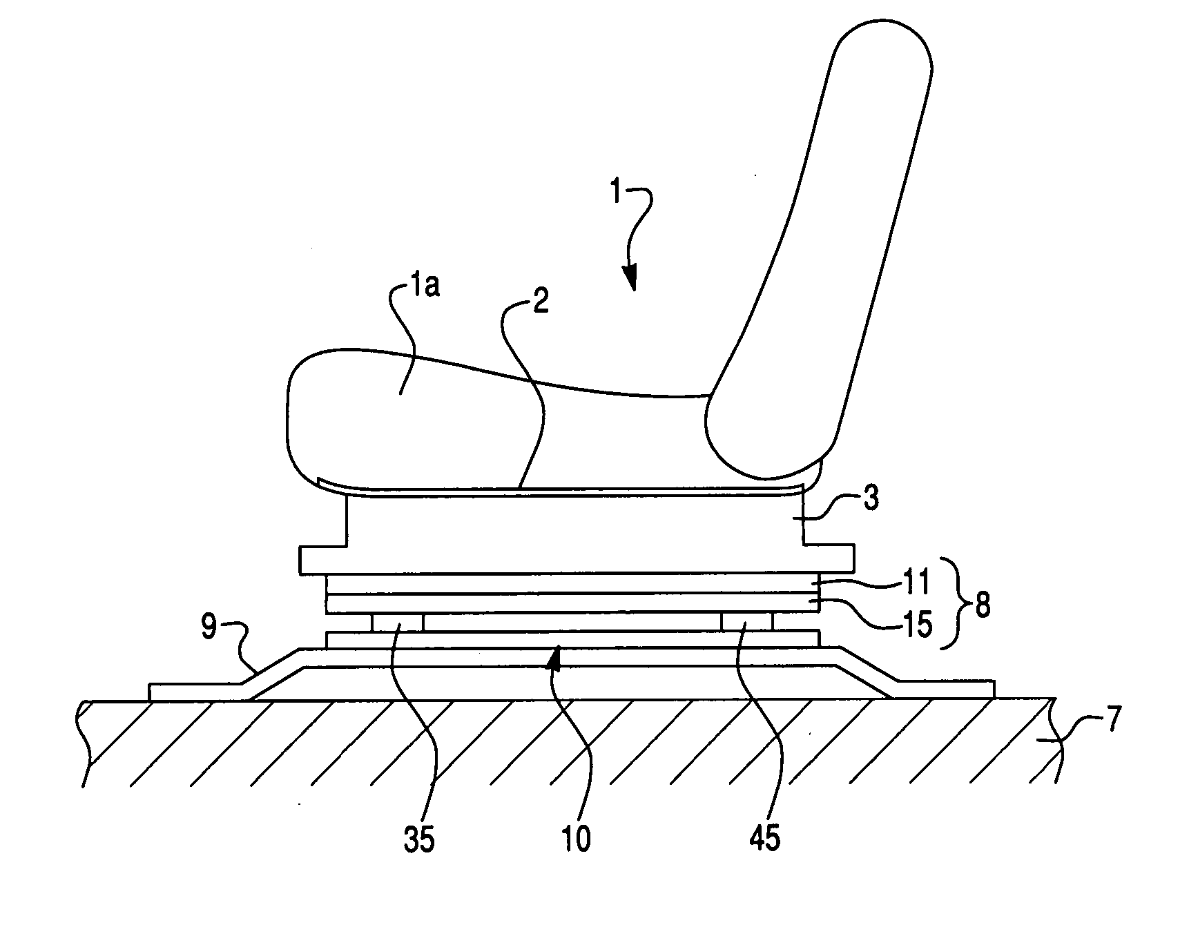
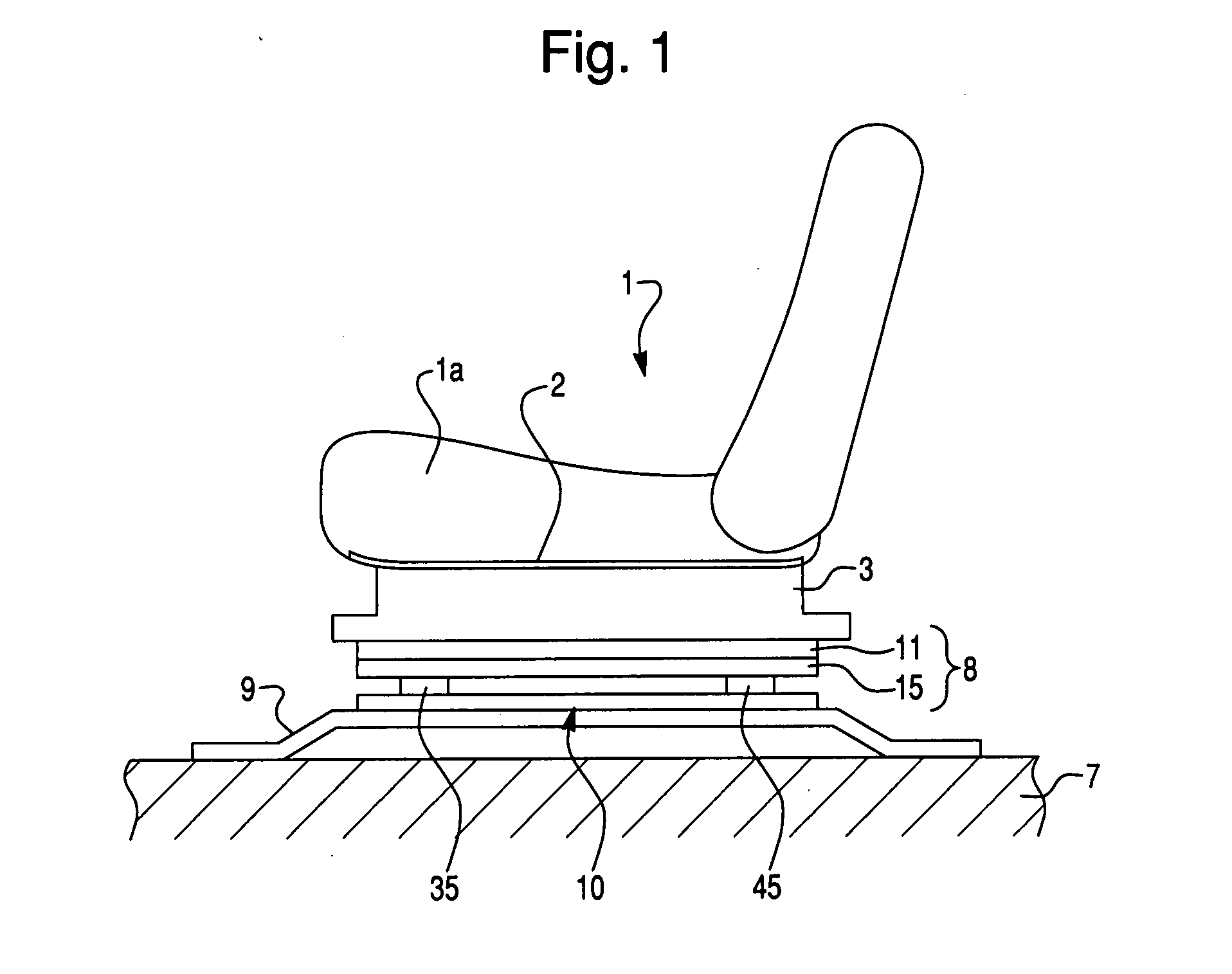
[0043] As shown in FIG. 1, a vehicle seat 1 has a seat cushion 1a on which an occupant sits, and a seat pan 2 made of a steel plate which is disposed beneath the seat cushion 1a to entirely cover the under surface of the seat cushion 1a. Under the seat pan 2, a pair of side frames 3 (only one of which is shown in FIG. 1) extend downwardly from the seat pan 2 and are spaced apart from each other at a predetermined distance in the lateral (left-to-right) direction of the vehicle. Each side frame 3 is disposed to extend in the longitudinal (front-to-rear) direction of the vehicle. Disposed on the lower ends of the side frames 3 are seat rails 8 (only one of which is shown in FIG. 1), respectively. Each seat rail 8 is a combination of an upper rail 11 which is fixed to the lower end of the side frame 3 and a lower rail 15 which is arranged to slide relative to the upper rail 1...
PUM
 Abstract
Description
Claims
Application Information