Synchronous oscillators

a technology of synchronous oscillators and oscillators, applied in the direction of pulse generators, pulse techniques, digital transmission, etc., can solve the problems of noise rejection, inability to compensate for losses, and inability to match

Inactive Publication Date: 2003-12-23
ANTHONY AESCHLIMANN
View PDF2 Cites 28 Cited by
  • Summary
  • Abstract
  • Description
  • Claims
  • Application Information

AI Technical Summary

Benefits of technology

Such a third feedback path in combination with the regenerative feedback of the synchronous oscillator may provide unpredicted and surprisingly advantageous effects. In particular, compared to a synchronous oscillator without NIC:
. In particular, compared to a synchronous oscillator without NIC:
The noise rejection sensitivity of the circuit may be improved;
The frequency stability of the circuit may be increased; and
The increase in any of the above may be up to about 30% or, in some cases, even greater.

Problems solved by technology

This is a result of the signal becoming so small that it cannot compensate for losses in the tank circuit.
However, compared to other circuits, a synchronous oscillator can provide a wide bandwidth, a high input sensitivity and a high noise rejection, which seems not to be matched by other circuits.

Method used


Image

  • Synchronous oscillators
  • Synchronous oscillators
  • Synchronous oscillators

Examples


first embodiment

The circuit of FIG. 10 may provide the same performance enhancement as the preceding embodiment, namely an increase in bandwidth, improved input sensitivity, improved noise rejection, and a reduction in jitter. In the circuit of FIG. 10, frequency multiplication by a factor of three occurs (i.e. domination by the second harmonic), instead of times four as in the

second embodiment

The second embodiment is also suitable for use in QPSK modems. For example, a 48 MHz oscillator frequency can automatically be converted to around 140 MHz IF frequency.

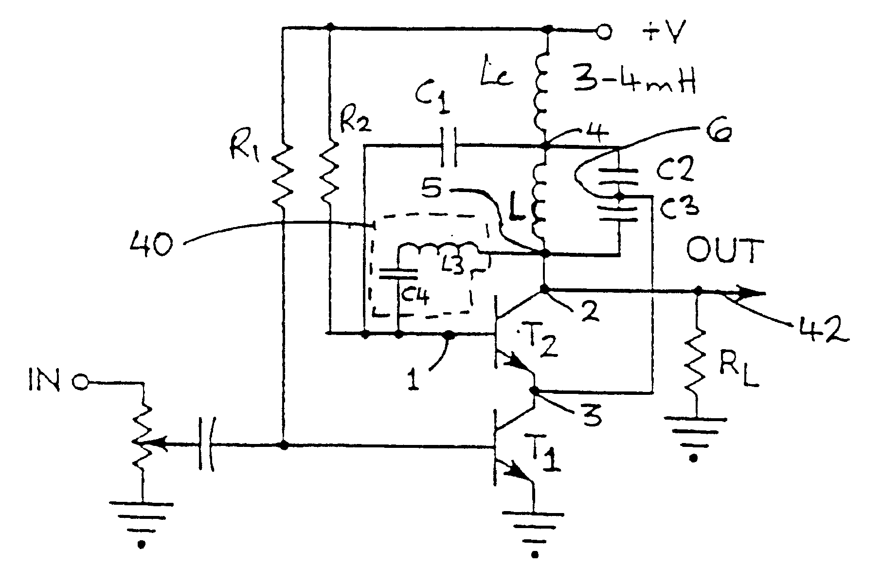
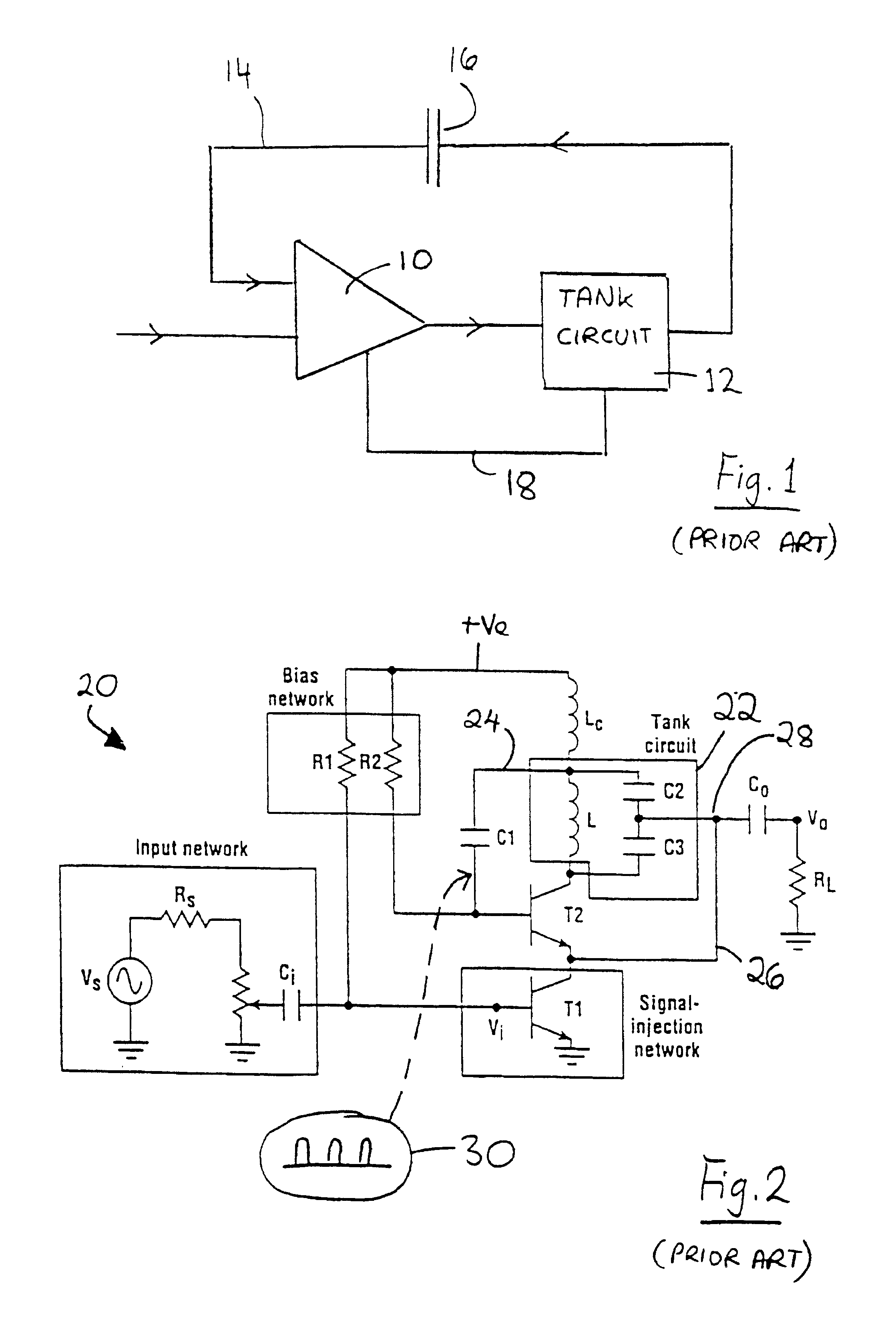
In the first and second embodiments, the synchronous oscillators are not phase corrected. However, if desired, the same negative impedance conversion feedback may be used in a coherent phase synchronous oscillator. For example, FIG. 11 shows such a coherent phase oscillator similar to FIG. 5, with the addition of the third feedback path 40 employing the inductor L3 and the capacitor C4. Such a circuit may provide the same enhancement of performance resulting from NIC, but with the addition of coherent phase. In standard circuits, no phase correction is available.

The above principle of NIC can be used in transmission lines, to increase their functional properties, in frequency, tracking range, noise rejection, and also provide better frequency stability and lower phase jitter. Also, along the same lines, it can be used...


PUM


Abstract

A modification of the synchronous oscillator is described, having regenerative positive feedback. The circuit includes an amplifier, a high-Q tank circuit, and a conventional synchronous oscillator feedback network. An additional feedback path provides a negative impedance conversion effect.

Description

This invention relates to the field of synchronous oscillators. Such oscillators are used as building blocks in a wide variety of circuit applications, including (but not limited to) clock recovery, modulation, encoding, decoding, signal detectors and discriminators, and direct sequence, spread spectrum (DSSS) systems. It is also ideal for broadband communications, in AM to FM conversion, FM to digital conversion, etc.BACKGROUND TO THE INVENTIONThe synchronous oscillator is well known, and is described, for example, in U.S. Pat. Nos. 4,274,067, 4,335,404 and 4,356,456 as well as in numerous papers published by the present inventor.The basic building blocks for a synchronous oscillator are shown, for example, in FIG. 1, and consist of an amplifier 10, a high-Q tank circuit 12, and a positive feedback path 14 through a feedback capacitor 16, and a second feedback path 18.The circuit uses regeneration to provide an output which is regeneratively linked to the input signal. By a combina...

Claims


Application Information

Patent Timeline
Patent Type & Authority Patents(United States)
IPC IPC(8): H03L7/08H03L7/083H03L7/24H03B5/08H03B5/12H04L7/027
CPCH03L7/083H03L7/24H03B5/1296H03B5/1203H03B5/1231H04L7/027H03B2200/0074
Inventor UZUNOGLU, VASIL
Owner ANTHONY AESCHLIMANN
Why Eureka
Try Eureka