Rotary switch mechanism for operation panel

a technology of operation panel and switch knob, which is applied in the direction of contact mechanisms, electrical devices, legends, etc., can solve the problems of limited space in which push switches, indicator light sources and the like can be provided, and achieve the effects of convenient design process, good attachability of switch knobs, and large spa

Inactive Publication Date: 2003-12-30
ZEXEL VALEO CLIMATE CONTROL CORP SAITAMA
View PDF7 Cites 28 Cited by
  • Summary
  • Abstract
  • Description
  • Claims
  • Application Information

AI Technical Summary

Benefits of technology

Accordingly, an object of the present invention is to provide a rotary switch mechanism for an operation panel that allows ample space on a printed boa

Problems solved by technology

For this reason, a problem arises with regard to utilization of the rotary switch in the quoted reference above in that the space in which push switches, the indicator light source and the like can be provided becomes limited since a large area of the printed board is occupied by the contact points.
In addition, s

Method used


Image

  • Rotary switch mechanism for operation panel
  • Rotary switch mechanism for operation panel
  • Rotary switch mechanism for operation panel

Examples


first embodiment

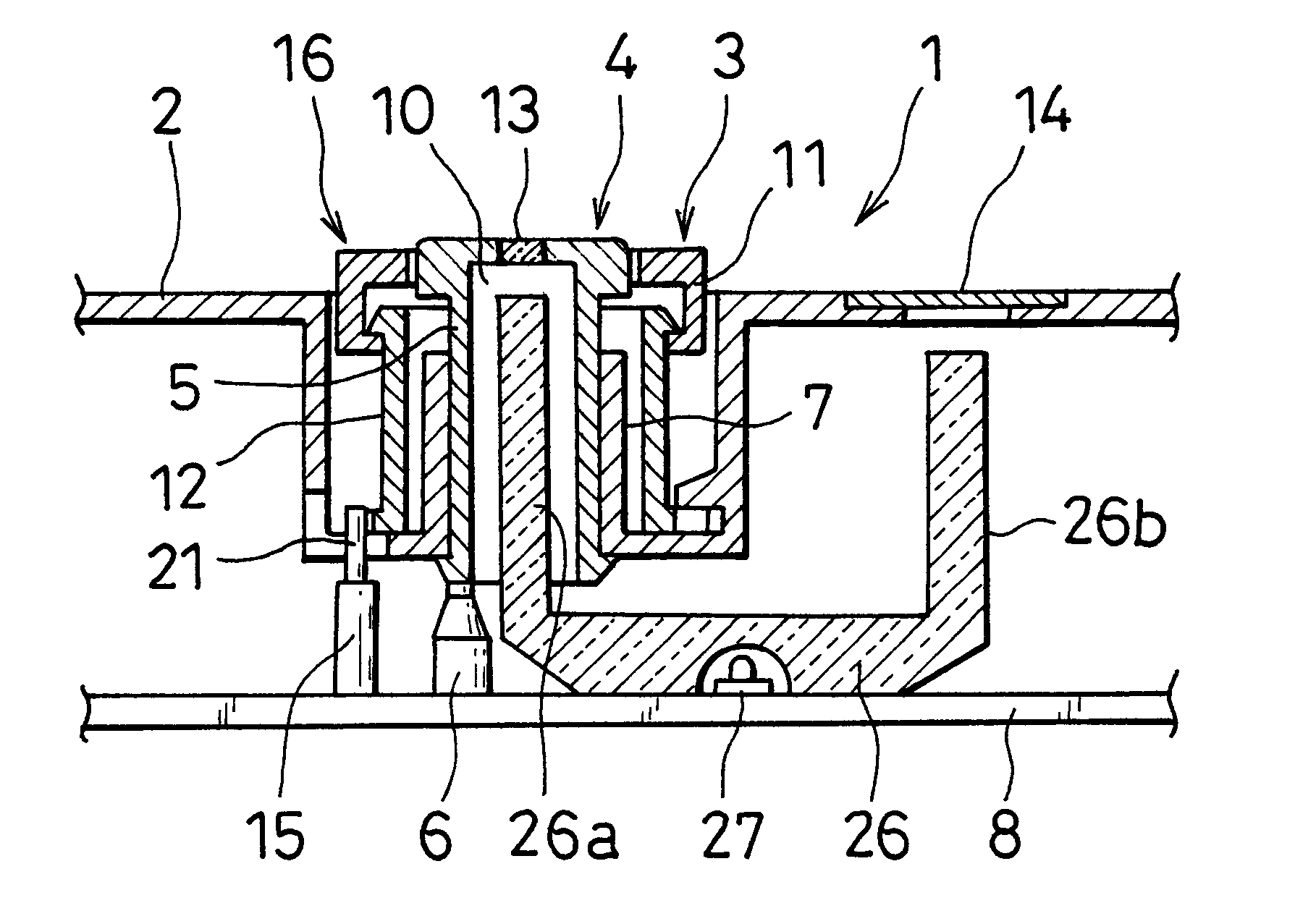
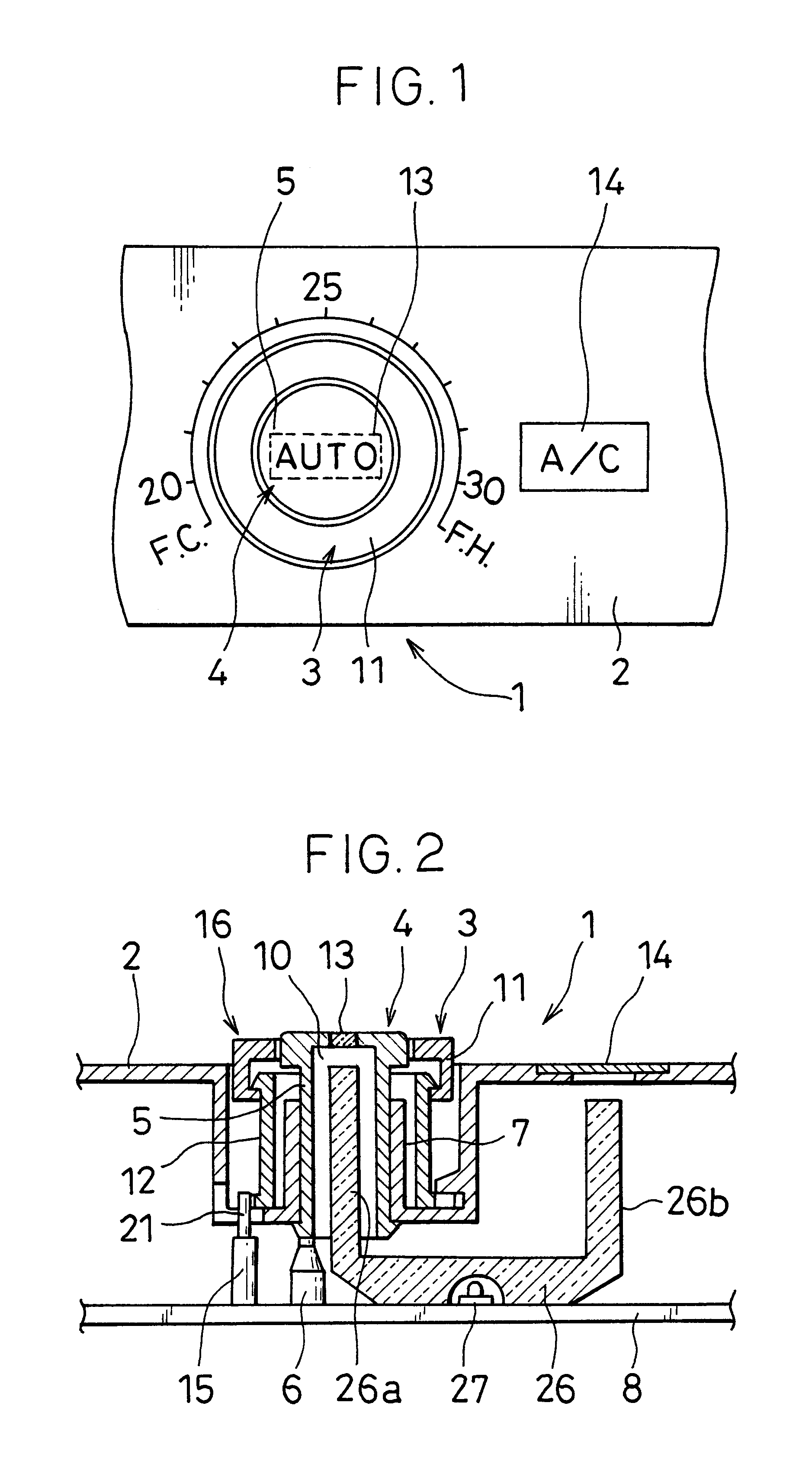
In addition, as illustrated in FIG. 2, adequate space for accommodating the push switch mechanism 4 is assured on the inside by employing the rotary switch mechanism 3 achieved in the first embodiment, and consequently, one of the light paths, i.e., a light path 26a of a light guide 26 can be housed within the push switch mechanism 4, and the space for accommodating the light source for the indicator 13 of the push switch mechanism 4 can be assured with ease. Furthermore, since the drive pieces 20 of the rotary knob 16 and the movable piece 21 of the detection switch 15 are not fixed to each other in this embodiment, the function of the detection switch 15 is not compromised as long as the movable piece 21 is set intersecting the rotational range of the drive pieces 20 even if a slight dimensional misalignment occurs during the mounting process, and thus, the mounting process can be simplified. It is to be noted that reference numeral 26b indicates a light path through which light i...

third embodiment

At a cylindrical drive unit 12B in the third embodiment illustrated in FIG. 5, drive pieces 20B are formed so as to project out along the axis of the cylindrical drive unit 12B over a specific interval along the circumference from a circumferential edge 19B at the other end of the cylindrical drive unit 12B. Since the drive pieces 20B do not project out along the radial direction in this embodiment, there is a likelihood of the measurement along the axial direction being greater than in the previous embodiments. However, a space is assured at the circumferential edge of the cylindrical drive unit 12B along the radial direction.

A rotary switch mechanism 3B shown in FIG. 6 includes a rotary knob 16B achieved by forming a dial unit 11B and the cylindrical drive unit 12B in the third embodiment and as an integrated unit with a light source 27 provided on the printed board 8 at the center of the rotary knob 16B. In addition, the rotary knob 16B in the embodiment is constituted of a trans...

fifth embodiment

In the fifth embodiment shown in FIG. 8, drive pieces 20D at a circumferential edge 19D at the other end of a cylindrical drive unit 12D constituting a rotary knob 16D are formed as gear teeth and the detection switch 15 is provided along the radial direction. Since the detection switch 15 is provided along the radial direction in this case, adequate space is assured along the axial direction.


PUM


Abstract

A rotary switch mechanism for an operation panel is designed such that the space on a printed board is ensured, the design of electronic parts on the printed board can be readily made, and the attachability of a switch is good. Drive pieces are arranged at predetermined intervals around the end of a rotary knob behind the operation panel, and a detection switch for detecting the passage and the direction of the passage of the drive pieces is disposed in or near the extent where the drive pieces move.

Description

TECHNICAL FIELDThe present invention relates to a rotary switch mechanism for an operation panel that may be utilized in, for instance, an air-conditioning system for vehicles.BACKGROUND ARTA rotary switch in the related art disclosed in Japanese Unexamined Patent Publication No. H 9-288934 comprises a switch board having a plurality of switch contact points, an elastic pressure application plate that includes a plurality of arm units and holds contact portions provided at the individual arm units on the switch contact points and a rotating body that is rotatably provided on the switch board and includes depressing portions provided at the lower surface of the switch board to come in contact with the arm units and thus push down the arm units.It is necessary to secure ample space in conjunction with a rotary switch utilized in an air-conditioning system for vehicles in the related art since push switches and the indicator light source are sometimes provided on the printed board wher...

Claims


Application Information

Patent Timeline
IPC IPC(8): H01H19/00H01H19/62H01H19/63H01H19/02H01H25/06H01H25/00H01H89/00
CPCH01H19/005H01H3/42H01H19/025H01H19/62H01H2219/0622H01H25/065H01H2019/006H01H2219/062H01H19/63
Inventor KOSEKI, AKIHIROHIROTA, KAZUHIKOMISUDA, HIROSHI
Owner ZEXEL VALEO CLIMATE CONTROL CORP SAITAMA
Why Eureka
Try Eureka