Vibrating hammer glove

a technology of vibrating hammer and hand, which is applied in the direction of manufacturing tools, portable power-driven tools, drilling machines, etc., can solve the problems of hand and skin injuries of users often times

Inactive Publication Date: 2004-01-06
DUNCAN DAVID
View PDF10 Cites 37 Cited by
  • Summary
  • Abstract
  • Description
  • Claims
  • Application Information

AI Technical Summary

Problems solved by technology

Injury to the user's hand and skin is often times experienced when using the erg

Method used


Image

  • Vibrating hammer glove
  • Vibrating hammer glove
  • Vibrating hammer glove

Examples


Embodiment Construction

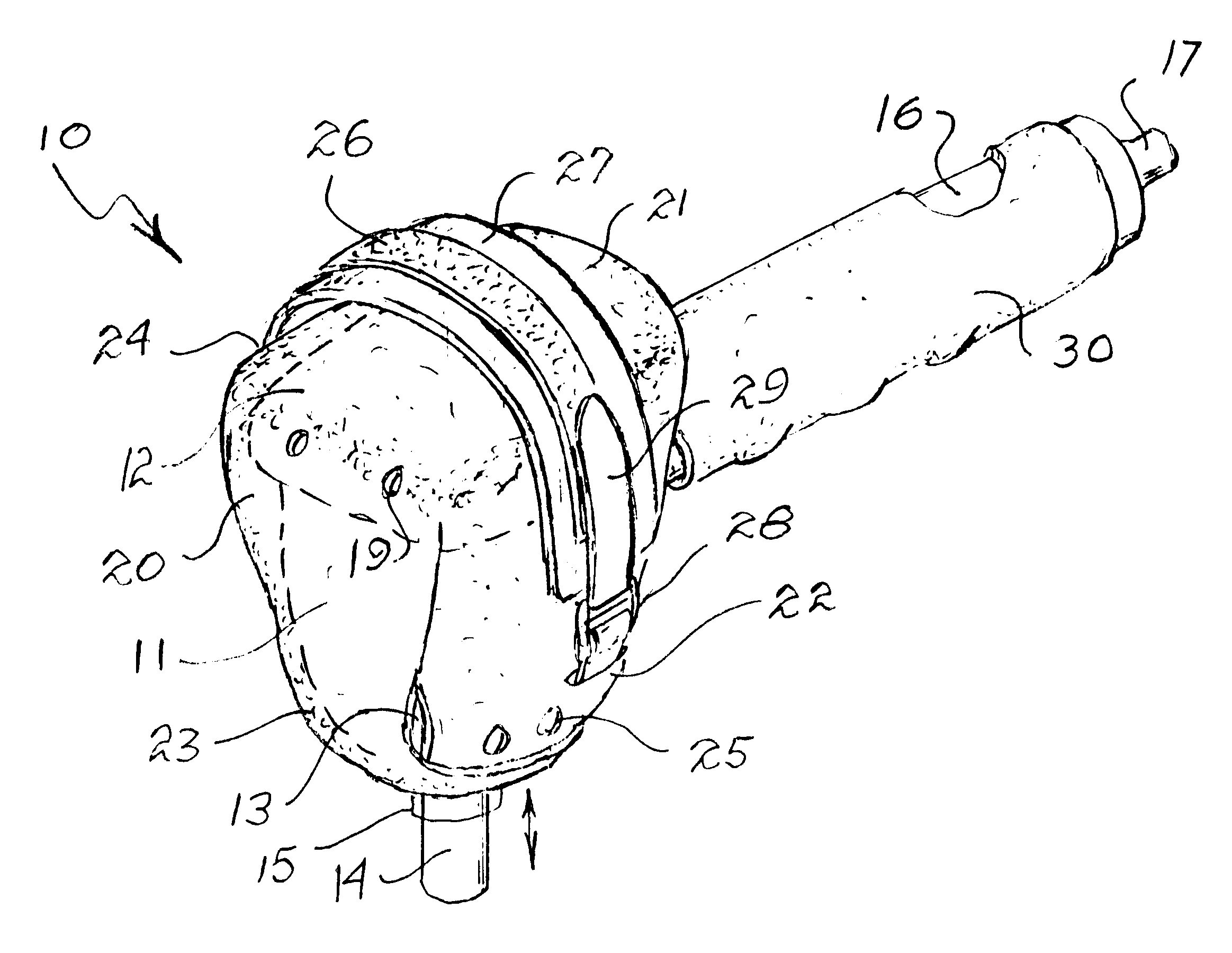
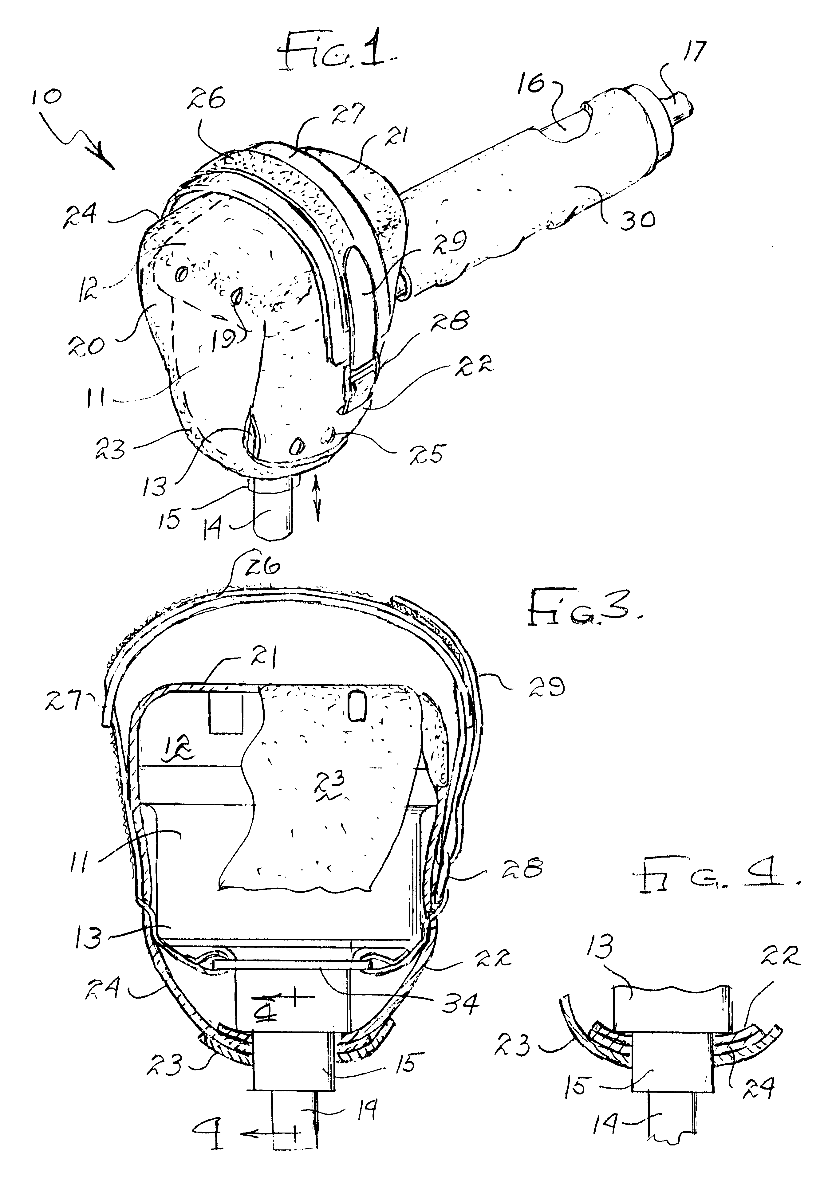
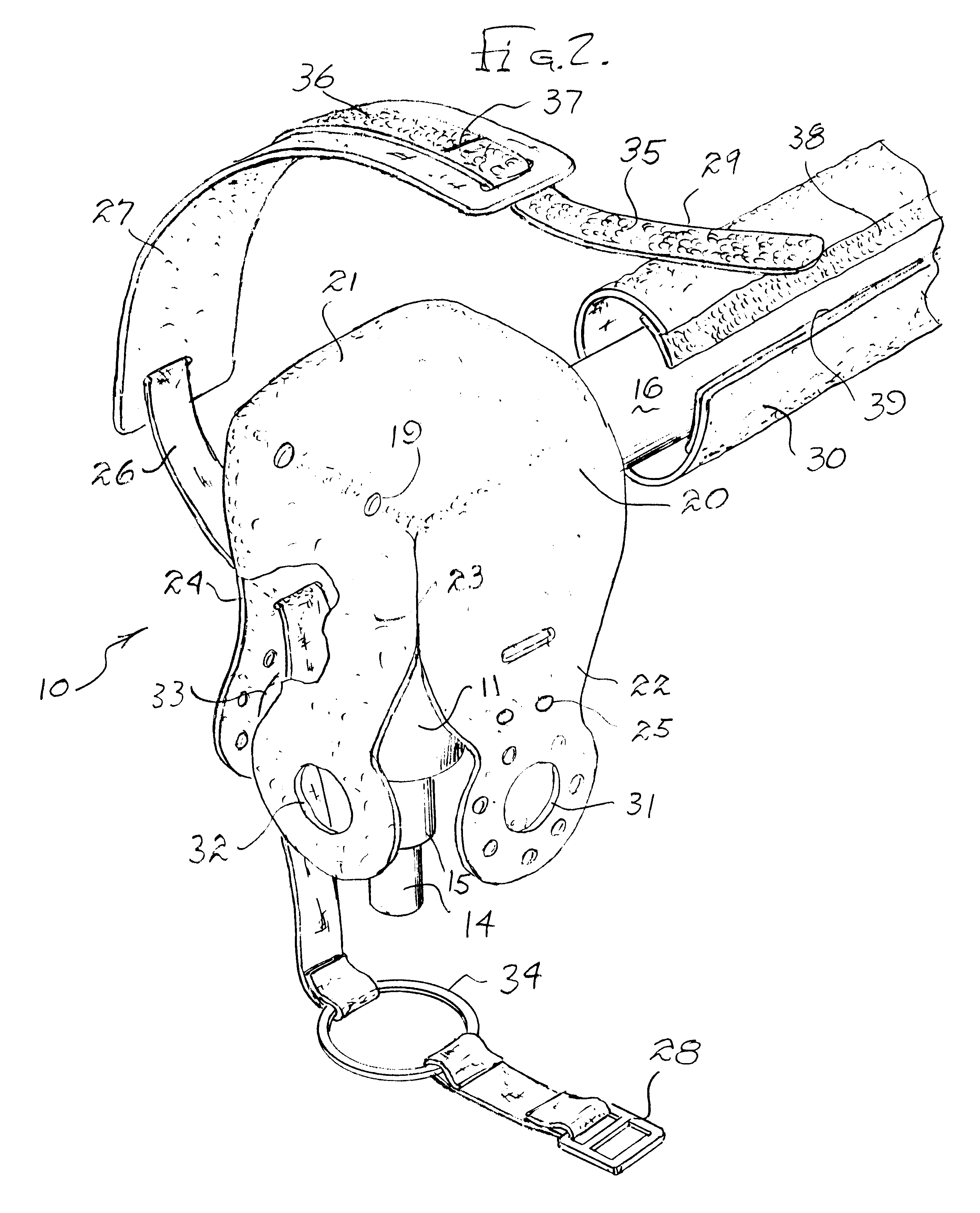
Referring to FIG. 1, the novel vibrating and impact hammer glove incorporating the present invention is illustrated in the general direction of arrow 10. The glove is employed for covering a motor housing 11 illustrated in broken lines. The housing includes a palm portion 12 and a motor portion 13. Downwardly projecting from the underside of the housing 11 is a reciprocating hammer head 14 adapted to move in and out of a fixture 15 when the motor is energized. Outwardly projecting from the rear of housing 11 is a handle 16 having a connector 17 adapted to be detachably connected with a source of pneumatic pressure. In one conventional form of impact hammer, the motor is operated pneumatically so as to cause the reciprocating hammer head 14 to move in and out in a rapid fashion from the fitting 15.

The glove 10 includes a housing cover 20 that has a section 21 covering the palm portion 12 of the housing and further includes downwardly depending attachment straps 22, 23 and 24 respecti...


PUM

PropertyMeasurementUnit
Heataaaaaaaaaa

Abstract

A vibrating hammer glove having a motor housing cover with a palm portion across the top of a hammer housing includes downwardly depending flaps which wrap around the housing and fasten with a stationary fitting. Further, a securement strap is trained through slots in the flaps so that the terminating ends thereof engage in a hook and pile fastener. A cushion between the palm portion of the cover and the underside of the strap provides additional shock and vibration absorption. A securement ring midway between opposite strap ends engages the stationary fitting so that the strap and glove are properly aligned, mounted, and retained on the housing. Air vents are provided in the palm portion and in the attachment flaps, whereby heat generated within the housing is dissipated to the environment.

Description

1. Field of the InventionThe present invention relates to the field of vibrating hand tools, and more particularly to a novel glove or padding assembly which fits over a conventional vibrating hammer normally held in the hand of the user and which protects the user's hand from injury.2. Brief Description of the Prior ArtIn the past, it has been the conventional practice to use vibrating hammers which include a housing for enclosing a motor and a reciprocating hammering member. The housing is held in the palm of the user's hand and when energized the reciprocating hammer is employed to impact against nails or other fastening devices in order to provide securement. Normally, the housing for the motor is composed of a metal which is hard and which transfers any impact loading and vibration into the hand and arm of the user. Also, the motor generates heat and the elevated temperature is passed through the metal housing to the hand of the user. Injury to the user's hand and skin is often...

Claims


Application Information

Patent Timeline
IPC IPC(8): B25F5/00
CPCB25F5/006Y10S16/12Y10T16/48Y10T16/476Y10T16/495
Inventor DUNCAN, DAVID
Owner DUNCAN DAVID
Why Eureka
Try Eureka