Motor vehicle utility tool

a technology for motor vehicles and utility tools, applied in manufacturing tools, coupling device connections, transportation and packaging, etc., can solve problems such as difficulty in hand, illness or infection, and the separation of wires in the trailer from the connector pins

Inactive Publication Date: 2005-10-25
ONTIVEROS STEVE
View PDF6 Cites 11 Cited by
  • Summary
  • Abstract
  • Description
  • Claims
  • Application Information

AI Technical Summary

Benefits of technology

[0017]A further object of the invention is to provide a tool for use with a large motor vehicle that is easy to use and store.
[0020]It is yet another object of the invention to provide a tool for use with a large motor vehicle that protects the electrical connectors of a commercial truck trailer from damage.
[0021]Another object of the invention to provide a tool for use with a large motor vehicle that protects the hands of the user from injury and dirt.
[0023]The tool of the present invention includes a handle portion connected to a u-shaped or forked portion at one end of the handle portion. The forked portion includes a pair of linear elements extending away from the point where the handle portion joins the forked portion. Each of the linear elements includes a recess in it to provide a means to prevent the tool from slipping while it is in use.
[0025]When a trucker, for example, wishes to disconnect the electrical connection between a truck cab and a trailer, he or she grasps the handle portion on one end and pushes the forked portion up around the electrical connection adjacent the trailer wall. The push bar abuts the trailer electrical connector to provide leverage for the disconnecting procedure. The lifting lug pushes the hinged cover on the trailer electrical connector up and away from the juncture of the trailer electrical socket and the truck electrical cable socket. Once the tool is in this position, the trucker pushes the handle towards the trailer wall. The linear elements engage the lugs on the side of the truck electrical connector and cause it to move horizontally away from the trailer electrical connection. This operation does not require the electrical lines to be manipulated in a manner that will cause the electrical wires and connecting pins in the trailer electrical system to break loose.
[0026]The tool of the present invention may also be used to separate the two air lines that connect a truck cab's air system to a trailer's air system by the incorporation of a pair of projections extending from one of the linear elements of the forked portion of the tool. The linear elements are configured to engage the connecting elements of the air systems, commonly known as “glad hands.” The projections engage the air connector on the trailer and are rotated to simulate the motion of a wrench. This operation causes the connecting elements to disengage from each other, thus enabling the user to separate the two air systems.

Problems solved by technology

This procedure can be difficult on a person's hands and can easily cause injury.
Often, after a lengthy trip, the socket and plug portions can be very dirty and can cause a mess.
Some of the dirt and grime collected on the electrical connectors could infiltrate the body through an opening in the skin and cause illness or infection.
Another problem associated with manually separating the electrical socket and plug on a motor vehicle system is that the process of pulling the two apart frequently includes “wiggling” of the socket and plug, which may lead to the wires in the trailer being separated from the connector pins.
Thus, some of the trailer's lights may not receive electricity or the supply of electricity will be interrupted, causing the trailer lights to blink or become inoperable.
This result leads to traffic citations being handed out to truckers as they carry out their work.
It may also lead to a potentially dangerous situation on the road under conditions of low visibility.
The tool disclosed in Stuart is permanently attached to the trailer and cannot be stored in the truck cab, nor can the tool be used to separate the air lines between the truck cab and the trailer.
Furthermore, it cannot be adapted for use on all models of trailer.

Method used


Image

  • Motor vehicle utility tool
  • Motor vehicle utility tool
  • Motor vehicle utility tool

Examples


Embodiment Construction

[0039]In the following description of the invention, reference is made to the accompanying drawings, which form a part thereof, and in which are shown, by way of illustration, an exemplary embodiment illustrating the principles of the present invention and how it may be practiced. It is to be understood that other embodiments may be utilized to practice the present invention, and structural and functional changes may be made thereto without departing from the scope of the present invention.

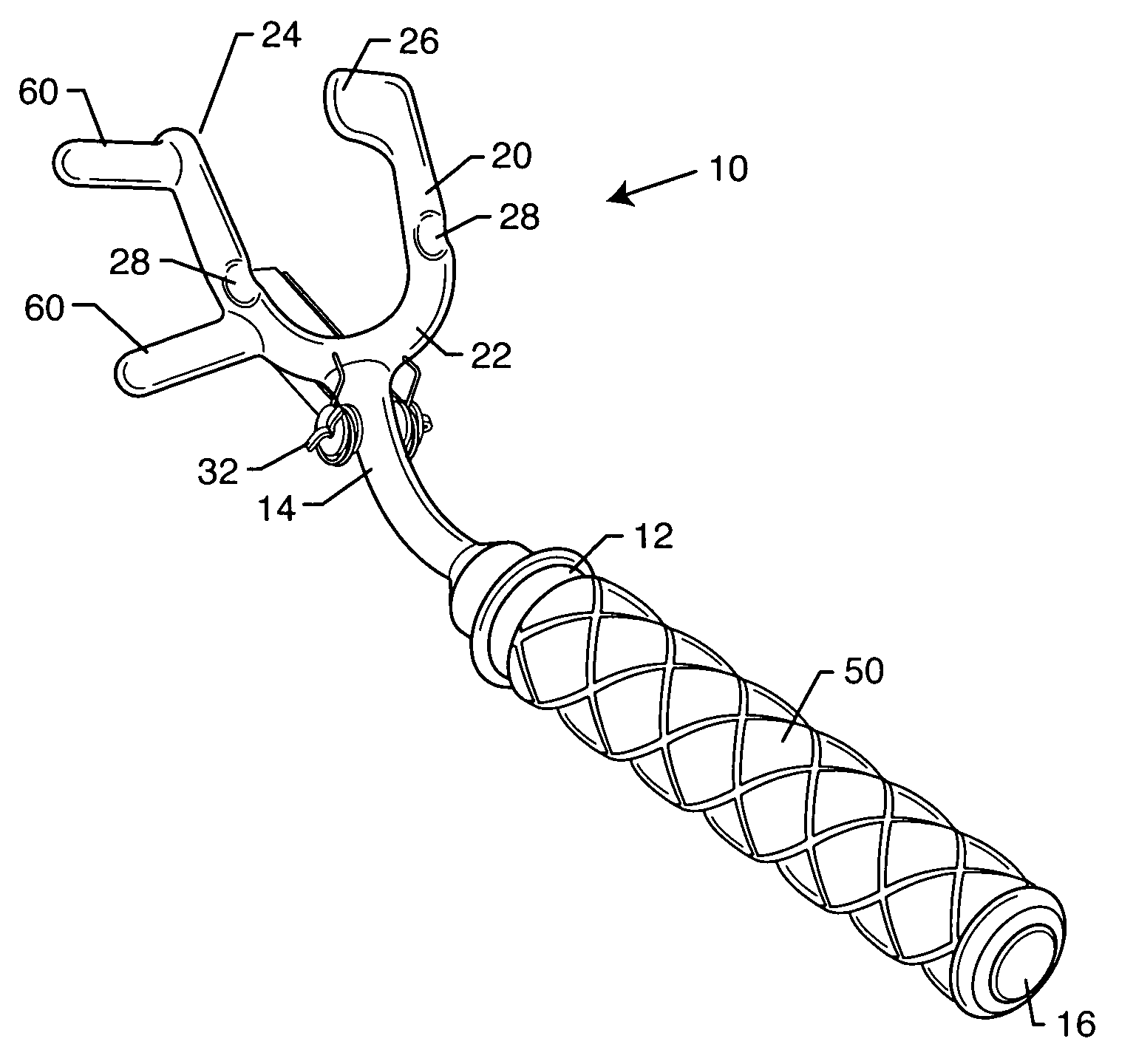
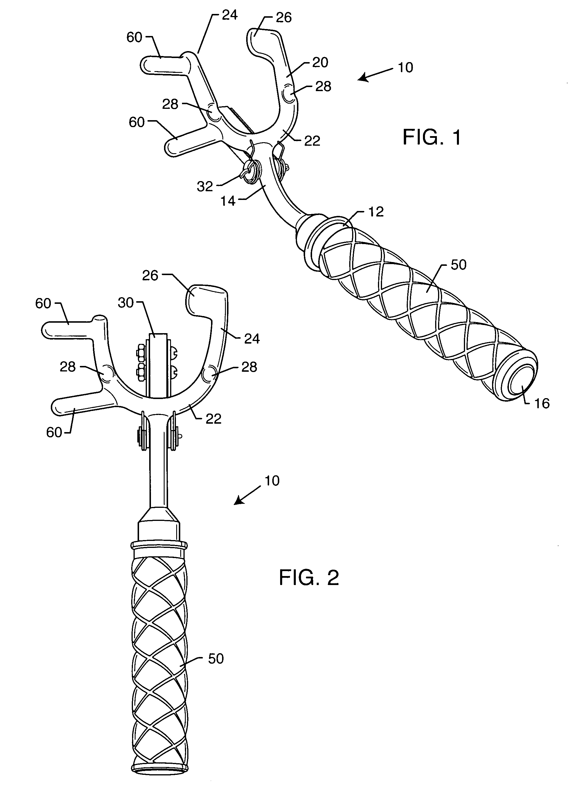
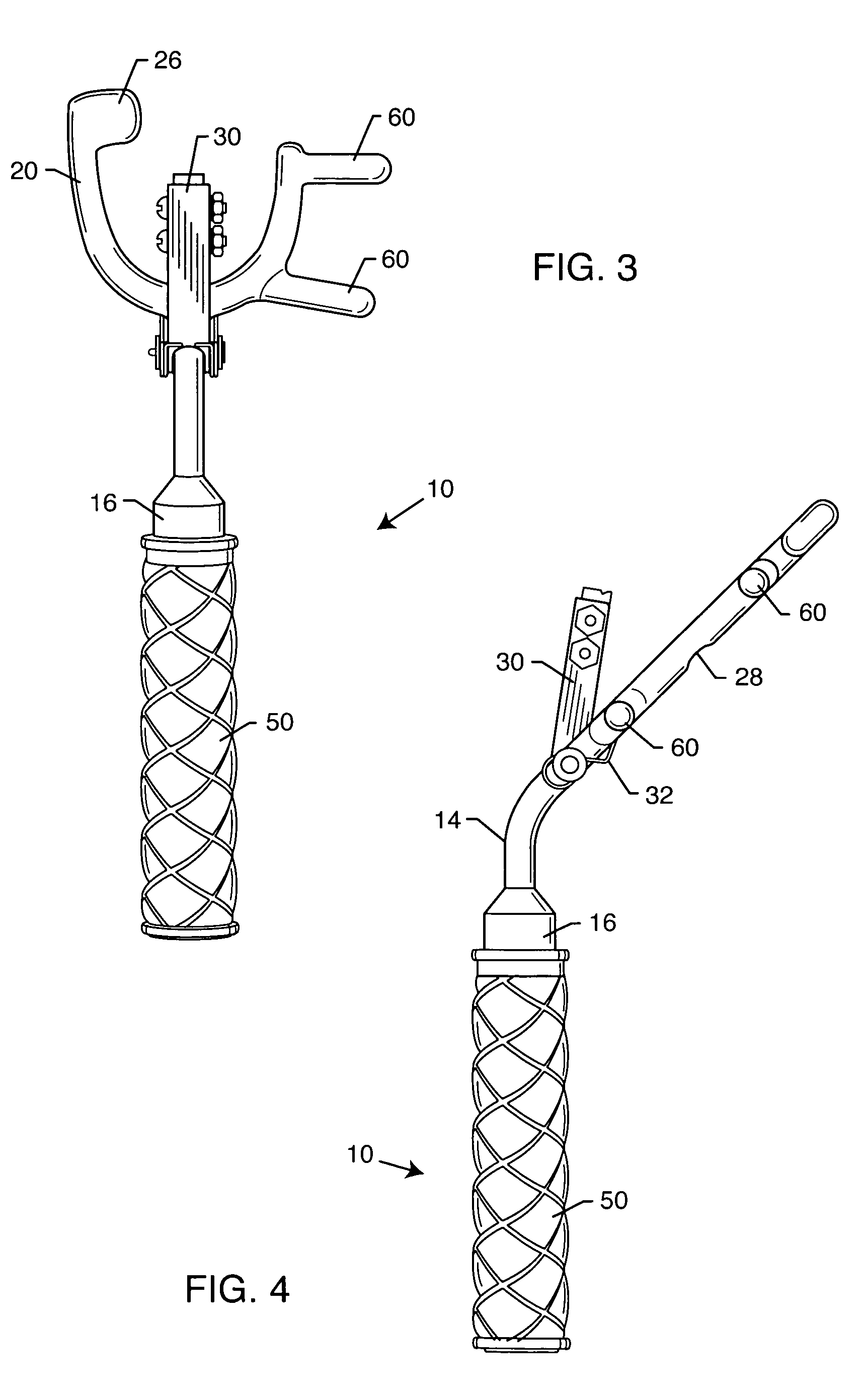
[0040]The preferred embodiment of a tool according to the present invention is illustrated in FIGS. 1–4 and is generally referred to by the reference numeral 10. The tool is preferably constructed of metal and is designed to be. Tool 10 includes a handle 12, which includes a straight portion 16 and a curved portion 14. Handle 12 also includes a gripping portion 50.

[0041]Attached to handle 12 is a fork 20, which includes curved element 22 and a pair of linear elements 24. At the end of one linear e...


PUM

PropertyMeasurementUnit
shapeaaaaaaaaaa
lengthaaaaaaaaaa
poweraaaaaaaaaa

Abstract

A tool for disconnecting the air and electrical connections between a motor vehicle and a trailer or a utility hookup station includes a handle and a forked portion. A spring-mounted push bar extends away from the handle and abuts the electrical connection socket of the trailer. A lifting lug on one of the prongs of the forked portion of the tool lifts the hinged plate away from the trailer's electrical connection. The tool is placed around the electrical connection adjacent the trailer and is pushed upward until it engages the trailer plug. The handle is then pushed towards the trailer, forcing the plug on the motor vehicle away from the socket. Projections extending from the forked portion of the tool can be used to engage the air line connectors between a motor vehicle and a trailer or a utility hookup station to separate the air lines.

Description

RELATED APPLICATIONS[0001]Not applicable.BACKGROUND OF THE INVENTION[0002]1. Field of the Invention[0003]The present invention relates to tools for use with motor vehicles. More particularly, it relates to a portable tool for use in disconnecting power and air lines between a motor vehicle, such as a truck cab, and a trailer that is towed by the motor vehicle, or some form of utility hookup apparatus.[0004]2. General Background and State of the Art[0005]The economy of our developed industrial nations relies heavily on the transport of goods by trucks and truckers. Many trailers that are towed by a truck, because of the nature of the goods they carry, require both power and air. Truck / trailer combinations actually have two air lines, one for service and one for the parking brake (a safety feature on modern trucks).[0006]During the last several years, travel by recreational vehicle (RV) has become increasingly popular. Nationwide, there are numerous camp grounds that provide space for...

Claims


Application Information

Patent Timeline
Patent Type & Authority Patents(United States)
IPC IPC(8): B25B27/14B25B27/00B25B27/02B60D1/62H01R13/629H01R43/26
CPCB25B27/0035B25B27/02B25B27/14B60D1/62H01R43/26Y10T29/537Y10T29/53704Y10T29/53943Y10T29/53909H01R13/629
Inventor ONTIVEROS, STEVE
Owner ONTIVEROS STEVE
Why Eureka
Try Eureka