Crash box collision damper for motor vehicle

a collision damper and box technology, applied in the direction of vibration dampers, superstructure connections, machine supports, etc., can solve the problems of insufficient force conductance through pins into the collision damper, the connection and the rigidity of the bumper cross member are not considered. optimal, the effect of the connection and the rigidity of the bumper cross member

Inactive Publication Date: 2004-01-06
WAGON AUTOMOTIVE
View PDF24 Cites 19 Cited by
  • Summary
  • Abstract
  • Description
  • Claims
  • Application Information

AI Technical Summary

Benefits of technology

Collision damping arrangements of the type herein are used for the protection of passengers of a motor vehicle during a collision, including head-on, rear end, and side collision. Energy released by the collision is absorbed and transferred to the passenger compartment in reduced form, or not at all. Such collision damping arrangements typically include a crashbox damping member between a bumper member and damping longitudinal members. The longitudinal members are connected to the passenger compartment and longitudinally absorb energy. The bumper member is typically a bumper-side cross member, the so-called bumper cross member, and extends perpendicularly to the longitudinal members. The crashbox damper member is located between the bumper and the longitudinal member and is longitudinally deformably compressible in response to longitudinal force application, to absorb collision energy, particularly at low speed, without deformation of the longitudinal member, to minimize frequency of replacement of the latter, which is expensive. The present invention is directed to improvements in the noted intermediate crashbox damper member.
In one aspect of the invention, in particular in the case of a laterally shifted head-on collision, the bumper cross member, arched in accordance with the strake, is selectively deformed in the longitudinal direction on the side facing the inner side of the vehicle body, where the force is applied first or is strongest at the onset, without the main part of the crashbox damper member being deformed at this time. The preliminary path realized according to the invention ensures that in the case of a laterally shifted head-on collision, the forward mounting surface of the crashbox damper member initially arranged at an acute angle to the rear mounting surface lines up parallel or approximately parallel to the lead mounting surface. At the onset of deformation, the collision damping arrangement remains intact, and its deformation in the longitudinal direction for the purpose of energy absorption starts only after the bumper cross member has been considerably deformed toward the inside in the particularly vulnerable area towards the center of the vehicle body. The function of the crashbox collision damper is retained even in the case of a laterally shifted head-on collision, and the passenger compartment remains optimally protected.
In a coordinated alternative of the doctrine of the invention, the forward mounting surface of the crashbox damper member on the bumper cross member is shaped so that the opposing facing surface on the bumper cross member can be arranged at a considerable angle range without problem. Instead of a pin bearing used in the prior art, a bearing based on a cap in the form of a spherical segment or arch in a similar fashion is used. The bumper cross member may be axially bolted or welded without problem. The base of the cap in the transition to the remainder of the crashbox damper member aft thereof is a fold which permits asymmetrical buckling, with the remainder of the crashbox damper member aft thereof remaining intact at initial force application in the case of a laterally shifted head-on collision in a similar fashion as noted above. The result of this asymmetrical buckling or sinking of the cap into the body of the hollow crashbox damper member is that the fixed connection between the bumper cross member and the crashbox damper member is not severed, but instead is retained even in the case of a laterally shifted head-on collision.

Problems solved by technology

The requirements regarding the material and design of such collision damping arrangements are therefore considerable.
However, such a pin bearing presents problems with regard to the technology of the connection and the rigidity of the bumper cross member.
In addition, the force conductance by means of the pins into the collision damper is not optimal.

Method used


Image

  • Crash box collision damper for motor vehicle
  • Crash box collision damper for motor vehicle
  • Crash box collision damper for motor vehicle

Examples


Embodiment Construction

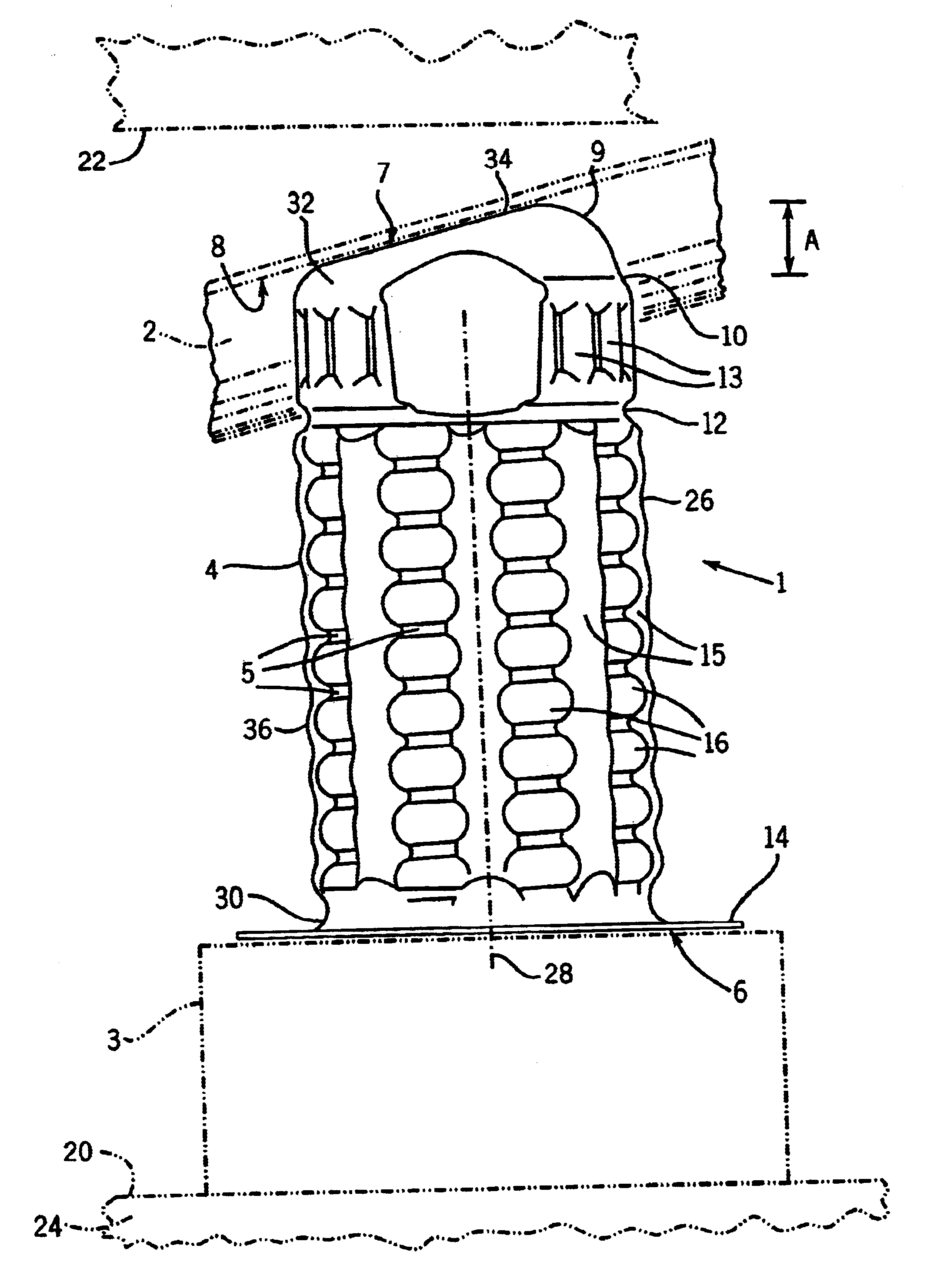
As noted in the above general description, the collision damping arrangement 1, FIG. 1, is intended for use in motor vehicles for the purpose of energy absorption in the case of a collision of the vehicle 20 with an obstacle 22. The collision damping arrangement 1 may be arranged at various locations in the vehicle, such as front, rear, or the sides. The task of the collision damping arrangement is to absorb as much motion energy as possible during a collision and convert it into deformation work, so that damage to the passenger compartment 24 of the vehicle body is kept to a minimum. In FIG. 1, collision damping arrangement 1 is used for energy absorption in the case of a head-on collision of the vehicle with an obstacle. The collision damping arrangement includes crashbox damper member 26 arranged between front bumper cross member 2 and the vehicle longitudinal member 3 at the front side of the latter. Longitudinal member 3 extends in the longitudinal direction of the vehicle and ...


PUM


Abstract

An automotive crashbox damper member (26) has a sequenced pre-collapse surface (34) providing sequential energy absorbing compression such that at application of longitudinal (28) force, longitudinal compression initially occurs at the pre-collapse surface (34), prior to compression of the remainder (36) of the crashbox damper member (26). In one embodiment, the pre-collapse surface (34) is a mounting surface (7) beveled (40) in roof-like fashion to a frontmost leading edge (38) over the end (32) of the crashbox damper member (26). In another embodiment, the pre-collapse surface (34) is a mounting surface (7) formed as an arched cap (11) in the form of a spherical segment over the end (32) of the crashbox damper member (26).

Description

This application claims priority from German Patent Application No. DE 10115512.3, filed Mar. 28, 2001, incorporated herein by reference.BACKGROUND AND SUMMARYThe invention relates to a collision damping arrangement for motor vehicles for absorbing energy in a collision of a motor vehicle with an obstacle.Collision damping arrangements of the type herein are used for the protection of passengers of a motor vehicle during a collision, including head-on, rear end, and side collision. Energy released by the collision is absorbed and transferred to the passenger compartment in reduced form, or not at all. Such collision damping arrangements typically include a crashbox damping member between a bumper member and damping longitudinal members. The longitudinal members are connected to the passenger compartment and longitudinally absorb energy. The bumper member is typically a bumper-side cross member, the so-called bumper cross member, and extends perpendicularly to the longitudinal member...

Claims


Application Information

Patent Timeline
Patent Type & Authority Patents(United States)
IPC IPC(8): B60R19/24B60R19/34F16F7/12B60R21/00
CPCB60R19/34F16F7/12B60R2021/0023
Inventor BECK, MANFRED
Owner WAGON AUTOMOTIVE
Why Eureka
Try Eureka