Boom support arm and use thereof

a technology of supporting arm and boom, which is applied in the direction of water cleaning, hydraulic engineering, construction, etc., can solve the problems that the flexible boom system cannot tolerate the shear stress that is developed at these attachment points, and achieve the effects of reducing the frequency of replacing terminal boom sections, and preventing damage to the floating boom system

Inactive Publication Date: 2009-12-29
GUNDERBOOM
View PDF11 Cites 0 Cited by
  • Summary
  • Abstract
  • Description
  • Claims
  • Application Information

AI Technical Summary

Benefits of technology

[0007]A third aspect of the present invention relates to a method of inhibiting damage to a fixed terminus of a floating boom system that includes the steps of: providing a boom support arm of the present invention; providing a floating boom system having a fixed terminus that is secured to a shoreline structure, the floating boom system comprising a plurality of flotation units and a curtain suspended from the flotation units; and connecting a portion of floating boom system to the boom support arm, between the fixed terminus and the second end of the support arm, using one or more connectors; wherein the boom support arm supports the portion of the floating boom system and thereby inhibits damage to the floating boom system as the boom system oscillates between high and low water levels.
[0008]The effect of the boom support arm is to more gradually taper the sloping of the boom from its point of connection to a fixed on-shore support to the high or low water level and, more particularly, to support the weight of the boom in this region. As a result of supporting a portion of the boom located between the fixed terminal end of the boom and the second end of the support arm, much stress is alleviated from the point of connection to the fixed on-shore connection. The support arm will either eliminate or at least minimize the frequency of replacing terminal boom sections as a result of fatigue and failure caused by such stress. This will save the site operator significant expense of replacing parts as well as avoid the need to shut down water intake systems during repair.

Problems solved by technology

The flexible boom systems often cannot tolerate the shear stresses that are developed at these attachment points as a result of the cyclical rising and falling of water column caused by tidal effects or adverse weather-related wave action.

Method used


Image

  • Boom support arm and use thereof
  • Boom support arm and use thereof
  • Boom support arm and use thereof

Examples


Embodiment Construction

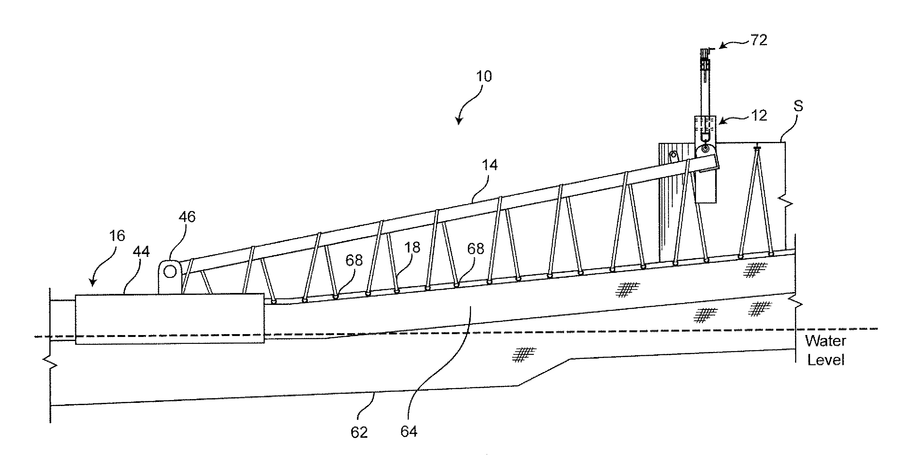
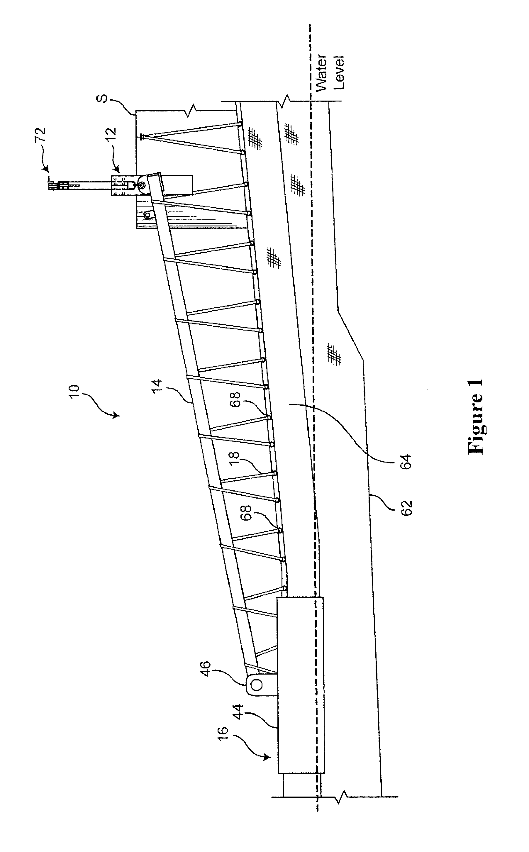
[0016]The present invention relates generally to a boom support arm that is intended to support a portion of a floating boom system between an end of the boom support arm and the terminal end of the boom curtain. In particular, the boom support arm can inhibit or, preferably, completely prevent failure of the terminal end of the curtain, which would otherwise occur in response to oscillation of the floating boom system between high and low water levels.

[0017]Referring now to FIG. 1, the boom support arm 10 generally includes a frame 12, support arm 14, flotation assembly 16, and one or more connectors 18. In use, shown in FIG. 1, the boom support arm 10 is intended to support a floating boom system 60 that is characterized by a curtain 62 having a hood portion 64 that contains a plurality of flotation billets as is known in the art. The curtain includes a terminal section 66 that is connected to a fixed, shoreline structure S. The curtain is preferably formed of a flexible fabric ma...


PUM


Abstract

A boom support arm that includes: a frame having a coupling positioned above a high water level; a support arm having a first end and a second end, the first end being pivotally coupled to the coupling on the frame for pivotal movement of the second end of the support arm between the high water level and a low water level; and a flotation assembly connected to the second end of the support arm. Use of the boom support arm in combination with a floating boom system for inhibiting damage to a fixed terminus of the floating boom system is also disclosed.

Description

[0001]This application claims the priority benefit of provisional U.S. Patent Application Ser. No. 60 / 524,201, filed Nov. 21, 2003, which is hereby incorporated by reference in its entirety.FIELD OF THE INVENTION[0002]The present invention relates generally to a boom support arm and its use for supporting a portion of a boom whose terminal end is fixed to a structure, which end would otherwise experience significant strain damage as a consequence of cyclical rising and falling of the boom under tidal conditions or under adverse wave conditions.BACKGROUND OF THE INVENTION[0003]Floating boom systems that are used in marine and aquatic environments sometimes must be affixed at one or both ends thereof to a fixed structure that is part of the natural or man-made shoreline. The flexible boom systems often cannot tolerate the shear stresses that are developed at these attachment points as a result of the cyclical rising and falling of water column caused by tidal effects or adverse weathe...

Claims


Application Information

Patent Timeline
Patent Type & Authority Patents(United States)
IPC IPC(8): E02B15/04
CPCE02B15/0814E02B15/08E02B15/0828
Inventor DREYER, HAROLD B.
Owner GUNDERBOOM
Why Eureka
Try Eureka