Polisher, pressure plate of the polisher and method of polishing

a technology of pressure plate and polisher, which is applied in the direction of grinding head, lapping machine, manufacturing tools, etc., can solve the problems of inferior goods being produced, damage to the wafer surface, and inability to uniformly polish, so as to reduce the frequency of replacement of ring pads, improve the flatness of wafers, and improve the polishing

Active Publication Date: 2015-07-07
LG SILTRON
View PDF42 Cites 0 Cited by
  • Summary
  • Abstract
  • Description
  • Claims
  • Application Information

AI Technical Summary

Benefits of technology

[0022]As described above, a polisher, a pressure plate of the polisher, and a method of polishing using the polisher according to the embodiment of the present invention have several effects as described in the following.
[0023]First, a pressure can be applied uniformly throughout a mounting block mounting a wafer thereon, accordingly improving flatness of the wafer.
[0024]Second, the pressure applied to the mounting block can be adjusted using an air bag. Therefore, frequency of replacement of a ring pad may be minimized. Also, a downtime of the polisher, during which the polisher cannot be operated for replacement of the ring pad, can be reduced. In addition, use of an abrasive cloth used for manufacturing a new ring pad may be reduced.
[0025]Third, since the pressure applied to the mounting block is adjusted using the air bag while maintaining a constant pressure of a cylinder, a polishing rate of the wafer can be uniformly maintained.
[0026]Fourth, connection and separation of the air bag are facilitated.
[0027]Fifth, the air bag may be manufactured with ease and at a low cost since it has a rubber plate form rather than a tube form.

Problems solved by technology

However, the above polisher according to a conventional art has some problems as follows. FIG. 2 illustrates a view showing the pressure applied to the mounting block in which the pressure plate is mounted with the wafer in the polisher shown in FIG. 1.
In this case, however, polishing may not be uniformly performed due to variation of the pressure, accordingly causing damage to the wafer surface.
That is, inferior goods may be produced.

Method used


Image

  • Polisher, pressure plate of the polisher and method of polishing
  • Polisher, pressure plate of the polisher and method of polishing
  • Polisher, pressure plate of the polisher and method of polishing

Examples


Embodiment Construction

[0040]Reference will now be made in detail to the preferred embodiments of the present invention, examples of which are illustrated in the accompanying drawings. The same structures and elements explained in the conventional art will be denoted by the same reference symbols as in the conventional art, and a detailed description thereof will be omitted.

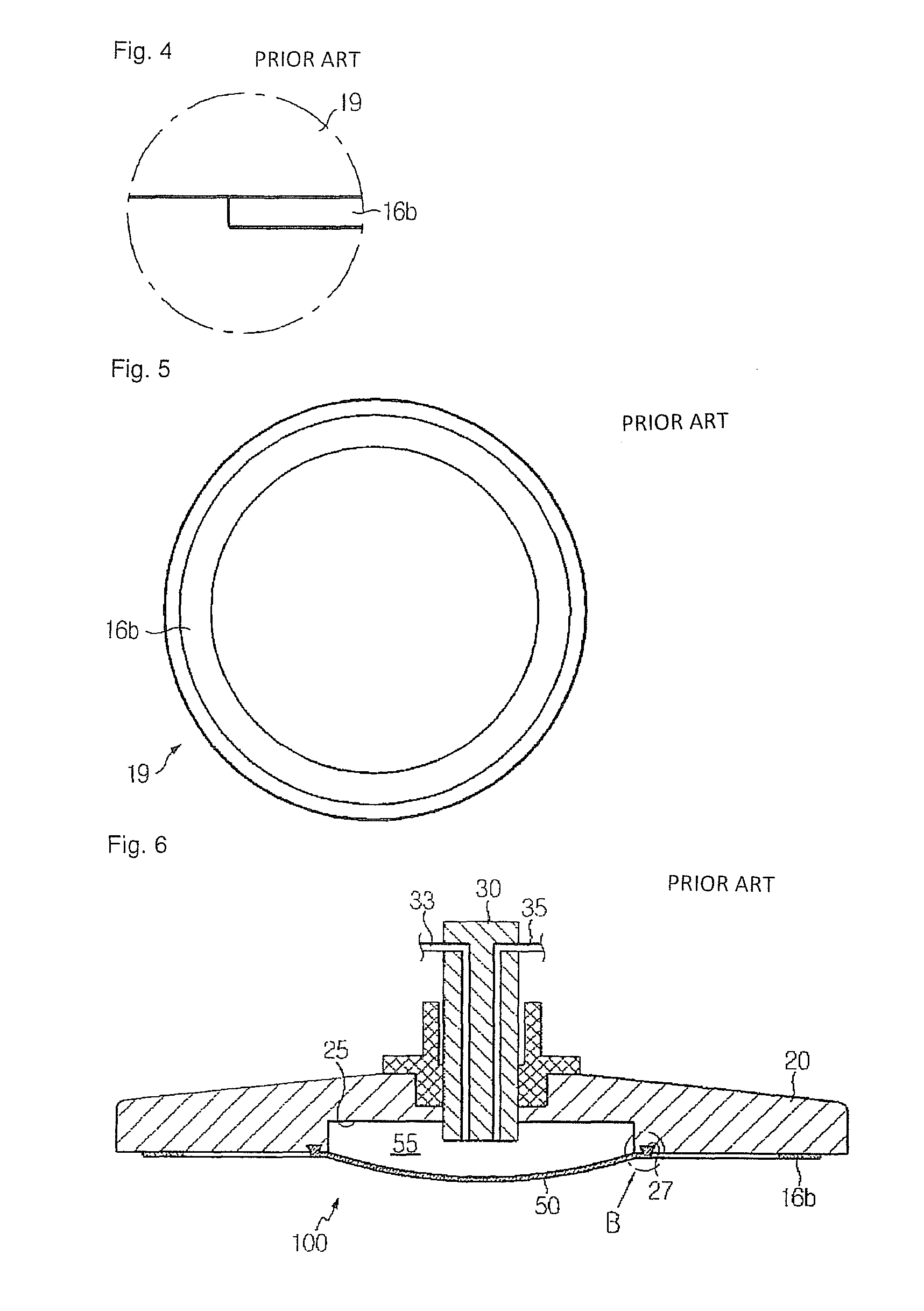
[0041]FIG. 6 illustrates a pressure plate of a polisher according to an embodiment of the present invention. The pressure plate of the polisher will be explained with reference to FIG. 6.

[0042]As shown in FIG. 6, the pressure plate 100 includes a main body 20, a central shaft 30 of the main body 20, an air bag 50 disposed in the center of a lower surface of the main body 20, and a ring pad 16b having an annular form arranged along the circumference of a lower surface of the main body 20.

[0043]In FIG. 6, the same reference numerals as in the description of FIG. 1 to FIG. 5 are used to indicate the same structures and elements shown in F...


PUM

PropertyMeasurementUnit
thicknessaaaaaaaaaa
circumferenceaaaaaaaaaa
pressureaaaaaaaaaa

Abstract

A polisher, a pressure plate (20) of the polisher, and a method of polishing are disclosed. The pressure plate (20) includes a main body, an air bag (50) mounted to one surface of the main body to adjust a pressure applied from the main body to a polishing object, and a pad (16b) having a ring shape, mounted along a circumference of the one surface of the main body.

Description

TECHNICAL FIELD[0001]The present invention relates to a polisher, a pressure plate of the polisher and a method of polishing, and more particularly to a polisher equipped with a pressure plate, the polisher capable of applying a uniform pressure through a wafer mounting block, minimizing the frequency of replacement of a ring pad, maintaining a uniform polishing rate of a wafer, improving flatness of the wafer, and facilitating manufacturing and connection and separation of an air bag, and a method of polishing using the polisher.BACKGROUND ART[0002]Polishing is one of the processes for manufacturing a wafer, performed by polishing a wafer so as to reduce a thickness thereof by about 10 μm to remove damaged portions generated in a previous process and adjusting localized light scatter (LLS) and haze while minor-surface polishing a surface of the wafer.[0003]FIG. 1 illustrates a perspective view showing a polisher according to a conventional art. Hereinafter, the polisher will be des...

Claims


Application Information

Patent Timeline
Patent Type & Authority Patents(United States)
IPC IPC(8): B24B49/00B24B37/04B24B41/00
CPCB24B37/042B24B41/002B24B9/08B24B13/00
Inventor KIM, HONG GILMIN, PAN GI
Owner LG SILTRON
Why Eureka
Try Eureka