Nozzle-type steam trap

a steam trap and nozzle technology, applied in the direction of steam traps, mechanical equipment, etc., can solve the problems of affecting the stable operation of factories, affecting the efficiency of facilities, and reducing the quality of products, so as to reduce the amount of co2, increase efficiency, and save energy

Active Publication Date: 2021-01-07
ECO FIRST
View PDF0 Cites 1 Cited by
  • Summary
  • Abstract
  • Description
  • Claims
  • Application Information

AI Technical Summary

Benefits of technology

[0022]According to the present invention, a nozzle-type steam trap including an orifice nozzle, a venturi nozzle, or a tunnel structure resistance nozzle sufficiently exerts a drainage valve function because, even when a pressure difference between a drain-water inlet side and a drain-water outlet side of each small-diameter tube-shaped bore fluctuates, a drain water seals the small-diameter tube-shaped bore and the steam is thus suppressed from passing through the small-diameter tube-shaped bore. Consequently, it is possible to achieve increased efficiency, energy savings, a reduction in CO2, and the like in factories without wasting steam.
[0023]Moreover, according to the present invention, the steam trap is compatible with various usage environments in factories, plants, and the like because the steam transport channel and the drain-water drainage channel of the steam trap are not on an identical axis.
[0024]In the nozzle-type steam trap according to the present invention, the steam transport channel includes a plurality of steam transport channels through which the steam flows into the system of the steam trap, the drain-water drainage channel includes a plurality of drain-water drainage channels through which the drain water is drained to the outside of the system of the steam trap from the extra-drain system drainage port, and the means for closing a selected one of the steam transport channels and a selected one of the drain-water drainage channels is provided to thereby determine passages for the steam and the drain water. Consequently, it is possible to introduce the nozzle-type steam trap according to the present invention to a steam transport system and a drain-water drainage system in any circumstances and to achieve an improvement in productivity and a reduction in costs of the steam trap because it is not necessary to order to produce various types of steam traps in accordance with various usage environments in factories, plants, or the like.
[0025]In addition, since the nozzle-type steam trap according to the present invention includes a means with which steam of a swirl flow is injected into the small-diameter tube-shaped bore, it is possible to suppress the nozzle from being clogged with rust, dust, and the like that flow in from the steam transport channel, which minimizes the replacement frequency of the nozzle. Consequently, it is possible to reduce loads of maintenance and inspection of the steam trap.

Problems solved by technology

For example, when a drain water remains inside steam-using facilities or inside a steam transport piping system, heating efficiency is decreased, productivity of the facilities is considerably decreased, and uneven heating due to drain drops may lead to inferior quality of products, which impedes stable operation of factories.
Moreover, such a drain water may cause extremely dangerous steam hammer in which a drain water remaining in a steam piping system agglomerates while flowing by being pushed by steam and a large agglomerate of the drain water collides with a bending portion of a pipe or a valve or steam hammer in which a drain water remaining in a steam piping system comes into contact with steam, the steam is thereby immediately condensed to have a zero volume and locally produces a vacuum state, and a surge of the drain water collides with a portion in the vacuum state, which may hinder safe operation of factories.
Thus, delay in operations and damage of movable portions as a result of repeated operations easily occur.
Moreover, it is difficult to suppress a large amount of steam leakage, and steam is thus significantly wasted.
In addition, the intermittent drainage in the steam traps that have the movable portions does not ensure the stable operation of steam-using facilities.
The drainage valve function in which a small-diameter tube-shaped bore is sealed by preferentially draining a drain water is, however, insufficient and causes the following problems.
However, fluctuation in steam pressure is actually large, and in particular, when an amount of the drain water is small or when an amount of generated drain water is suddenly increased or decreased due to warm air in an emergency, a high-pressure water injector of a desuperheater, or the like, it is not possible for the venturi tube 10 having a fixed bore diameter to follow such a sudden increase or decrease, leading to a problem in which steam passes through the venturi tube 10 and the drainage valve function is not exerted.
In such a circumstance, steam is wasted, and an increase in efficiency, an energy saving, and a reduction in CO2 in factories, which are required for existing steam traps, are failed to be achieved.
In addition, there is another problem in which mass production is not possible because, similarly to, for example, a steam transport pipe 7 and a drain-water drainage pipe 8 in FIG. 1, a steam inlet and a drain-water outlet of a nozzle-type steam trap are disposed on substantially identical axes or fixed at predetermined positions and it is thus necessary to order to produce various types of steam traps in accordance with various usage environments in factories, plants, or the like in which steam is used as a heating source via a heat exchanger.
Such a circumstance makes it difficult for steam traps used in large numbers in various factories, facilities, or the like to improve productivity and to reduce costs.
In addition, orifice nozzles, venturi nozzles, and tunnel structure resistance nozzles all have a problem in which a small-diameter tube-shaped bore becomes clogged with rust, dust, and the like that flow in from a steam transport system and that are small enough to pass through a screen.
As a result, the replacement frequency of each nozzle is increased, which increases loads of maintenance and inspection.

Method used


Image

  • Nozzle-type steam trap
  • Nozzle-type steam trap
  • Nozzle-type steam trap

Examples


Embodiment Construction

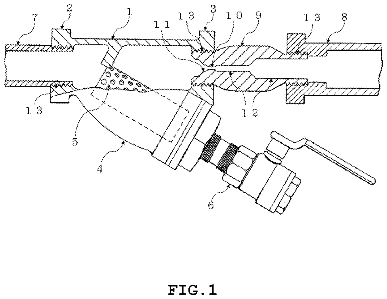
[0033]Hereinafter, regarding embodiments of the present invention, a venturi nozzle-type steam trap will be described, as a typical example, with reference to the drawings; however, the present invention is also applicable to general nozzle-type steam traps of the orifice nozzle type and the tunnel structure resistance nozzle type capable of performing continuous drainage. Note that the present invention is not limited to these embodiments, can be carried out by being variously modified within a scope not deviating from the spirit of the present invention, and is limited by only the technical concept disclosed in the claims.

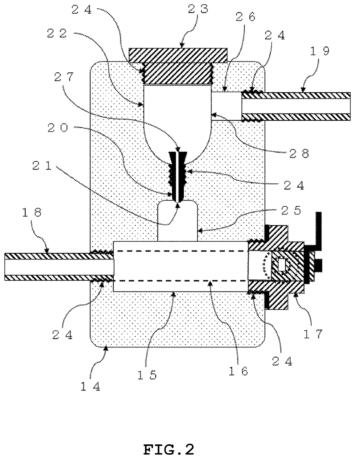
[0034]FIG. 2 is a schematic view illustrating a section of a horizontal strainer-included venturi nozzle-type steam trap according to an embodiment of the present invention, in which a means for sealing a venturi tube by using a drain water is provided, and a steam transport pipe and a drain-water drainage pipe are not on an identical axis.

[0035]A steam trap body...


PUM


Abstract

A nozzle-type steam trap including a venturi nozzle, an orifice nozzle, or a tunnel structure resistance nozzle minimizes the outflow of steam even when a pressure difference between a drain-water inlet and a drain-water outlet of each nozzle fluctuates, the steam trap being compatible with any usage environments and enabling maintenance and inspection to be easily performed. The nozzle-type steam trap including the venturi nozzle, the orifice nozzle, or the tunnel structure resistance nozzle includes a means for sealing the nozzle by using a drain water. The nozzle-type steam trap further includes a plurality of steam inflow ports and drain-water outflow ports and includes a closure means for determining, for a selected one of the steam inflow ports and a selected one of the drain-water outflow ports, passages of steam and drain water. More preferably, the steam trap includes a swirl flow formation means in the vicinity of the nozzle.

Description

TECHNICAL FIELD[0001]The present invention relates to a nozzle-type steam trap that automatically and continuously drains a drain water (condensed water formed by condensed steam) generated in steam-using facilities and a steam transport piping system between these facilities to the outside of the system in various factories, plants, or the like in which steam is used as a heating source via a heat exchanger, and particularly relates to a nozzle-type steam trap that includes a venturi nozzle, an orifice nozzle, or a tunnel structure resistance nozzle.BACKGROUND ART[0002]A large number of steam traps are used in various factories, plants, and the like in which steam is used as a heating source via a heat exchanger to automatically drain a drain water generated in steam-using facilities and a steam transport piping system between these facilities to the outside of the system.[0003]The use of steam traps in large numbers is to ensure appropriate temperature conditions in, first of all,...

Claims


Application Information

Patent Timeline
Patent Type & Authority Applications(United States)
IPC IPC(8): F16T1/34F16T1/16F16T1/38
CPCF16T1/34F16T1/38F16T1/16F16T1/386
Inventor KATSURA, TSUTOMUMASUTANI, TOMOHIRO
Owner ECO FIRST
Why Eureka
Try Eureka